1. Introduction
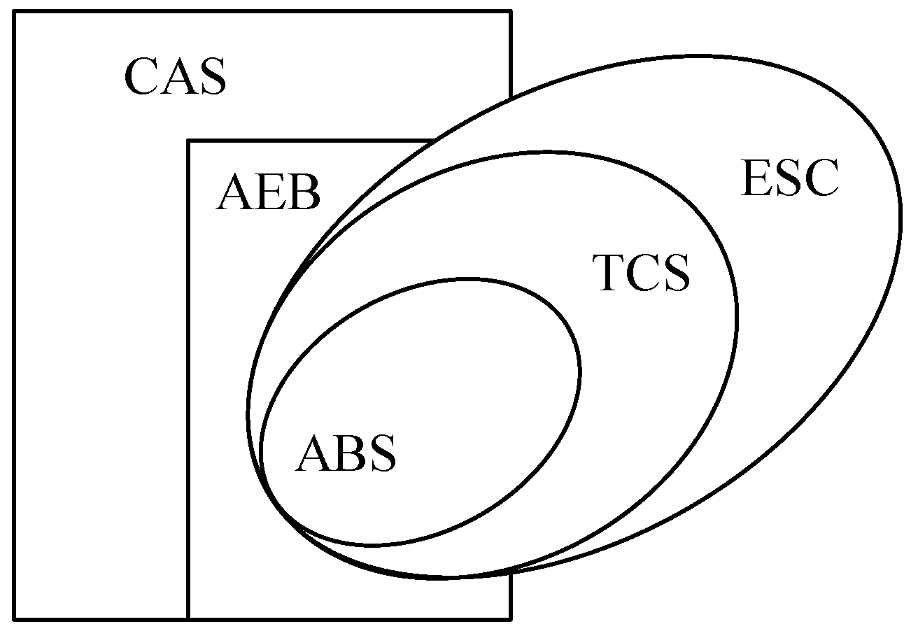
Recently, steering assistance technologies of the vehicle have been on the rise because of safety and legal requirements. Automakers are now urgently developing and announcing relevant safety functions, such as autonomous emergency braking (AEB), to highlight steering assistance. Basically, AEB is a kind of technology for collision avoidance systems (CASs). AEB can be treated as a one-dimensional CAS. However, a general CAS should cover not only one-dimensional collision avoidance, but also two-dimensional collision avoidance. Consequently, the CAS is a necessary function for steering assistance. According to Fildesa et al. [
1], the rear-end collision is 32% of all the car accidents in urban cities, especially in crowded traffic. Additionally, their results showed that by merely adding the AEB function, rear-end collisions can be effectively reduced by 38%. It is known that AEB is a one-dimensional approach for the CAS. However, in some city driving scenarios, certain highway driving is still required. Therefore, the two-dimensional CAS sparks the interest of this study. Generally, the presented CAS includes both one-dimensional and two-dimensional collision avoidance technology. The one-dimensional approach is similar to the AEB and the known adaptive cruise control (ACC). In addition, the two-dimensional approach is the basis of automatic steering. The CAS approaches are known as the advanced driver assistance systems (ADAS). They can decrease the fatigue of the driver and the possibility of accidents [
2]. For instance, when the ADAS prompt is considered as the distance up to the maximum, the driver does not pay any attention to it. If the distance is less than the minimum, the system will initiate one-dimensional braking automatically to avoid rear-end collisions. However, if there are unexpected obstacles or accidents that occur while driving, the system intervenes to avoid the collision. Therefore, the intelligence for driving intervention based on ADAS is important [
3].
Basically, the embedded system needs to intervene with control measures in a timely manner and thus utilizes two judgment principles: (a) avoid all collisions and (b) never perform a faulty intervention [
4,
5]. If the system causes a disturbance between the driver and the driving safety system of ADAS, it can cause an accident. Hence, the driving strategy prompts the driver to pay attention to the distance between vehicles when it is up to the maximum. Likewise, if it is less than the minimum, the system will intervene to avoid the collision by braking. The concept is similar to that employed in some intelligent control theories. This paper proposes a fuzzy-based control algorithm to maintain the braking force and its related safety. For evaluation, testing related strategies under real conditions leads to significant efforts and costs [
6,
7]. In this study, a hardware-in-the-loop (HIL) platform is used for evaluations. The inputs from the operator are real; however, the vehicle dynamics are virtual. This platform setup facilitates cost-effectiveness for full-scale evaluations. In this paper, these tools are employed to evaluate the control strategy and its corresponding performances.
3. Proposed System
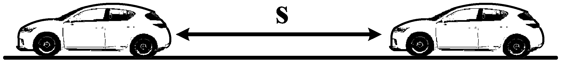
The timing of slamming on the brakes is according to the relative velocity and distance of the two vehicles. The rear-end collision system is usually evaluated according to the maximum distance. If the distance achieves the warning zone, the system will only initiate an alarm to the driver. Conversely, if it achieves the minimum limit, the system actively controls the vehicle to brake to avoid the collision.
Figure 2 shows the detection of the front and rear cars.
The key to one-dimensional AEB is the relative velocity
, the deceleration
of the front car, and the maximum braking acceleration
of the rear car. Note that
is the triggering speed,
is the ground speed of the front car,
s is the relative distance of the two vehicles. Therefore, the related motion equations are as follows:
Note that
and the target is
. In addition, the braking deceleration cannot take place beyond the maximum deceleration of the AEB. Otherwise, the traction force saturation will occur because of the nonlinear behavior of the tire’s dynamics. Safety is the first issue. The distance
, which is the collision avoidance zone, is set as
Then, according to the distance
, the system can invasively initiate emergency braking. However, the one-dimensional automatic brake causes different saturated and slippery tire conditions against the different velocities and distances of the front vehicle; therefore, it is immediately difficult to measure and compensate for.
Table 1 gives the proposed fuzzy limits. Under this table, the rear vehicle can have a performance that is more comfortable while the AEB is activated. This rule is based on a series of engineering tests and adjustments. Safety and comfort are the dilemmas of the one-dimensional automatic brake. Therefore, steering to avoid collision from two-dimensional motion control is then proposed. It improves the driving safety and energy efficiency.
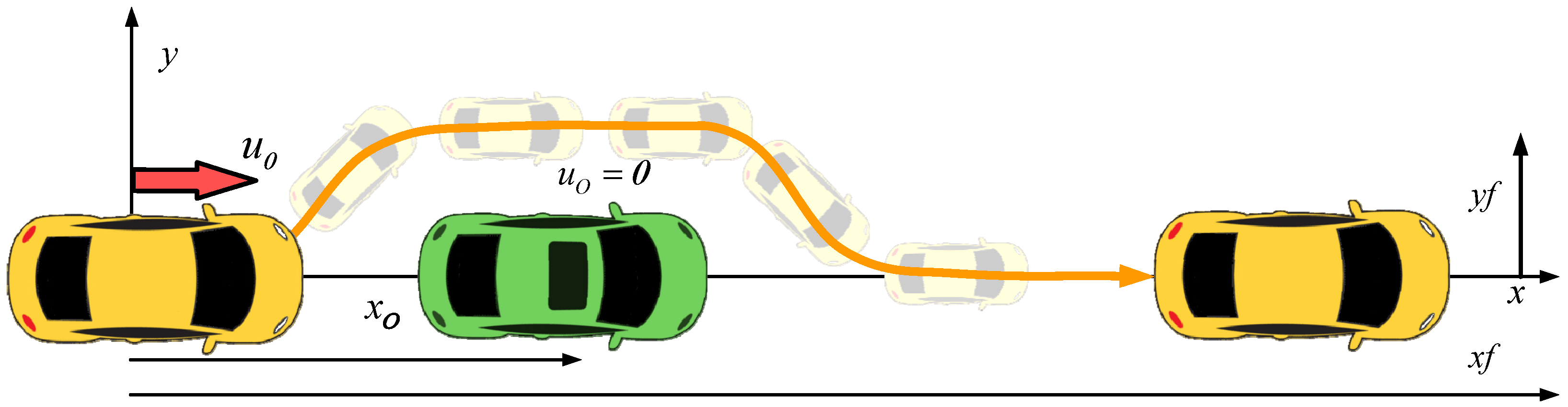
Figure 3 shows the vehicle changing lanes to avoid a collision. When steering to avoid a two-dimensional collision begins, the vehicle requires one or two instances of steering. Therefore, it will cause significant yaw moment. The vertical and horizontal tractive forces of the tires rapidly decline due to nonlinear saturation in case the vehicle is out of control and in danger of losing its tractive force when steering. Therefore, control is the key to avoiding two-dimensional collisions.
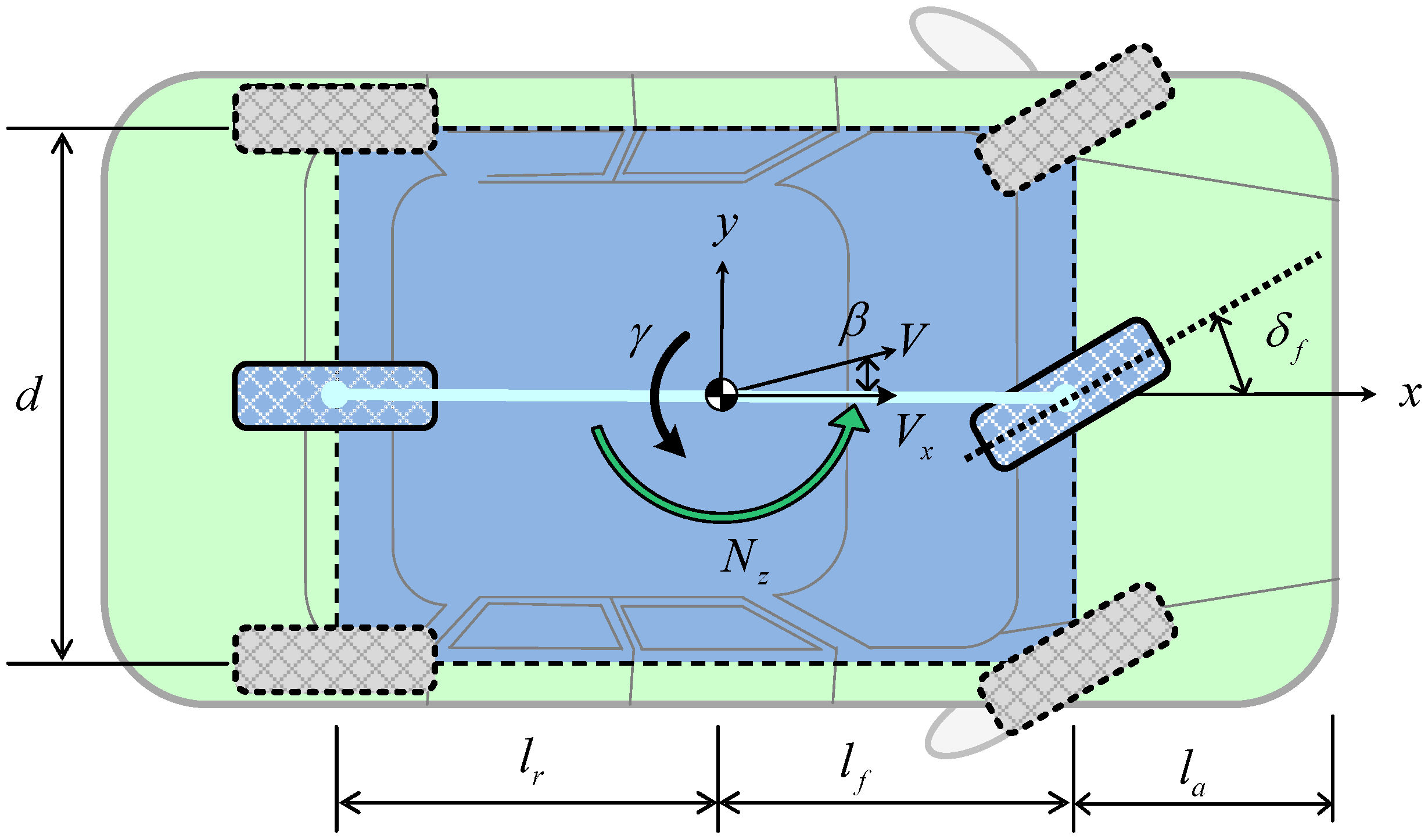
Figure 4 gives the model of the vehicle engaged in two-dimensional motion, and the vehicle of the motion equation is shown the following formula:
where β is the side slip angle, γ is the yaw-rate of the center of the vehicle’s mass,
M is its mass,
ay is the lateral acceleration, δ
f is the steering angle of the front wheels,
Vx is the longitudinal velocity of the vehicle,
In is the nominal moment of inertia.
Cf and
Cr are the cornering stiffness of the front and rear wheels.
and
are the wheelbase of the center of the front and rear wheels.
Nz is the active compensation torque.
Nd is the torque from environmental disturbances, such as crosswind. Let
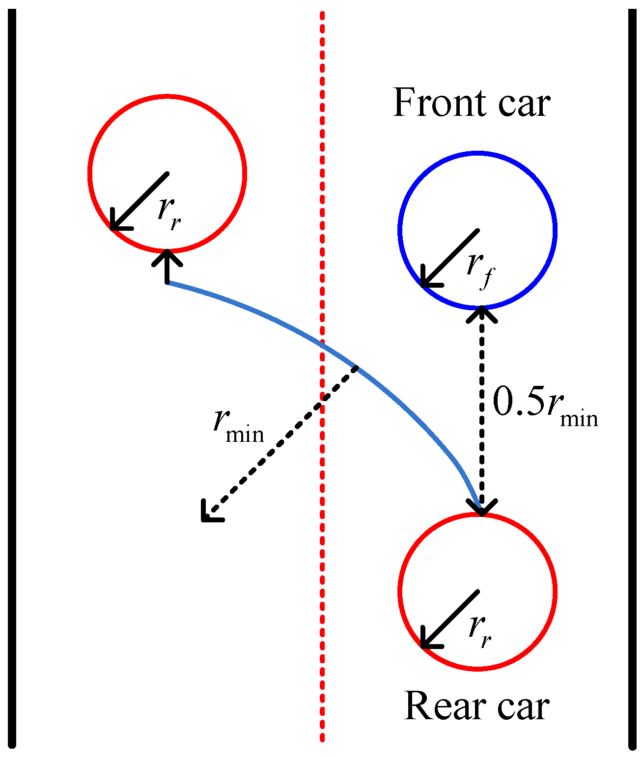
This paper proposed a solution to deal with two-dimensional CAS. Note that when the rear vehicle overtakes the front one by steering to avoid two-dimensional collisions,
and
are the safe radius of the front and rear cars, and
is the minimum radius of the rear steering. When the distance between vehicles is 0.5
, the system will automatically steer the steering wheel to avoid the collision by 30° or 45°, provided that the adjacent lane is clear. The steering schematic is shown in
Figure 5. Generally, the minimum steering radius follows the formula of geometric relationships.
Herein lies the equation
;
is the distance from the front bumper to the front wheels. The yaw moment can be controlled by the ESC. Stable steering of the vehicle produces the order of the yaw rate as
Here, k is the adjustable gain and is the low-pass filter. In this scheme, the yaw moment control should be guaranteed. Consequently, the ESC should be activated all the time. Otherwise, the vehicle may fall into an unstable scenario when performing an overtaking.
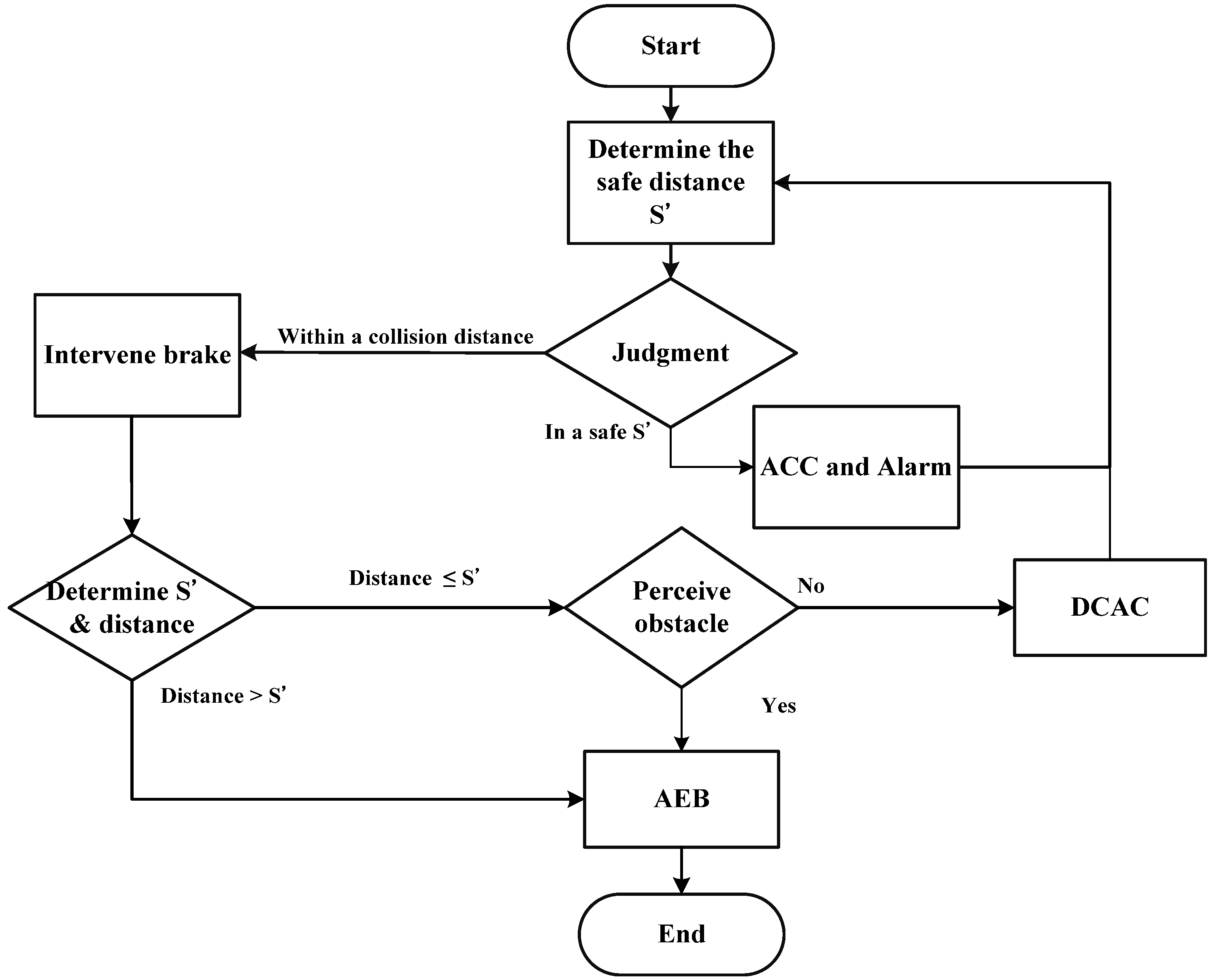
In this paper, the two-dimensional CAS is called the dynamic collision avoidance control (DCAC). It combines all the mentioned technologies in a dynamic situation.
Figure 6 shows the flowchart of the presented system. As can be seen in this figure, the presented system covers the functions of ACC and AEB. Additionally, the DCAC can achieve collision avoidance in a dynamic way. Thus, it appears to be an overtaking scenario; the rear vehicle should change its lane once or twice. Evaluations in the following section will be carried out to verify the proposed algorithm. Note that it has the potential to be employed on the Intelligent Transportation Systems (ITSs). For a wheeled vehicle with tires, our proposed approach, namely the DCAC, can be applied to trucks, buses, and even linked vehicles, such as railway trains. The proposed approach can be a foundation for modern autonomous vehicles. It endows the autonomous vehicles with nimble and reliable reactions on motion and safety regarding collision avoidance. Consequently, for further investigations at the next stage, the proposed approach can be applied to a full-scale autonomous vehicle for ground tests.
4. Evaluations with Hardware-in-the-Loop
The proposed approach was verified under the software CarSim (Version 8.03, Mechanical Simulation Corporation, Ann Arbor, MI, USA, 2012) with hardware-in-the-loop (HIL) packages. CarSim can provide the virtual model of the vehicles and simulate the conditions of different roads. The HIL provides the steering command from the operator and software to make some experimental scenarios. The commands such as steering the wheel and pedal are input directly from the hardware. In this paper, CarSim with the HIL setup is utilized to verify the correctness of the presented issues. The results combine both virtual vehicle model dynamics and real hardware inputs. The evaluations facilitate the cost-effectiveness on the experimental evaluations. Note that the HIL evaluation was mainly built for the purpose of testing different scenarios on real steering conditions. Hence, part of the simulation can employ real and/or virtual devices in order to achieve a cost-effective and safe experimental environment. No doubt the HIL can evaluate an engineering problem in a cost effective way, especially for severe and aggressive steering tests.
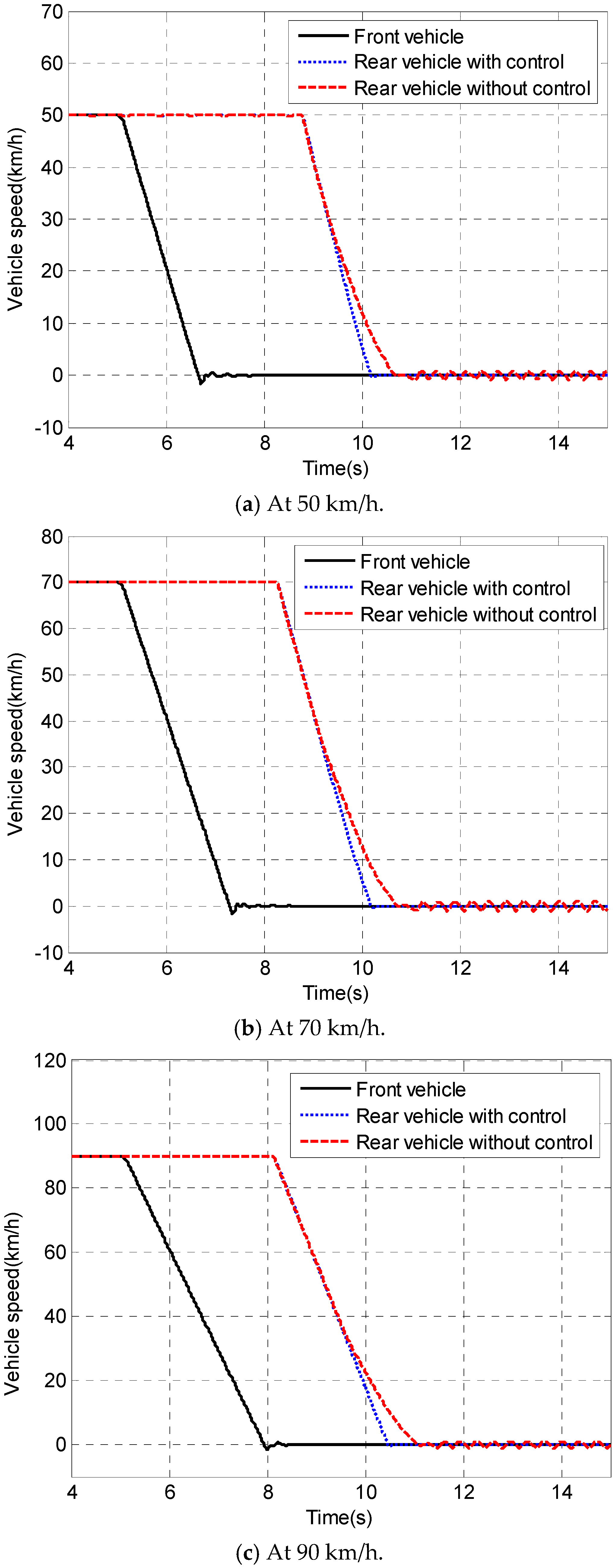
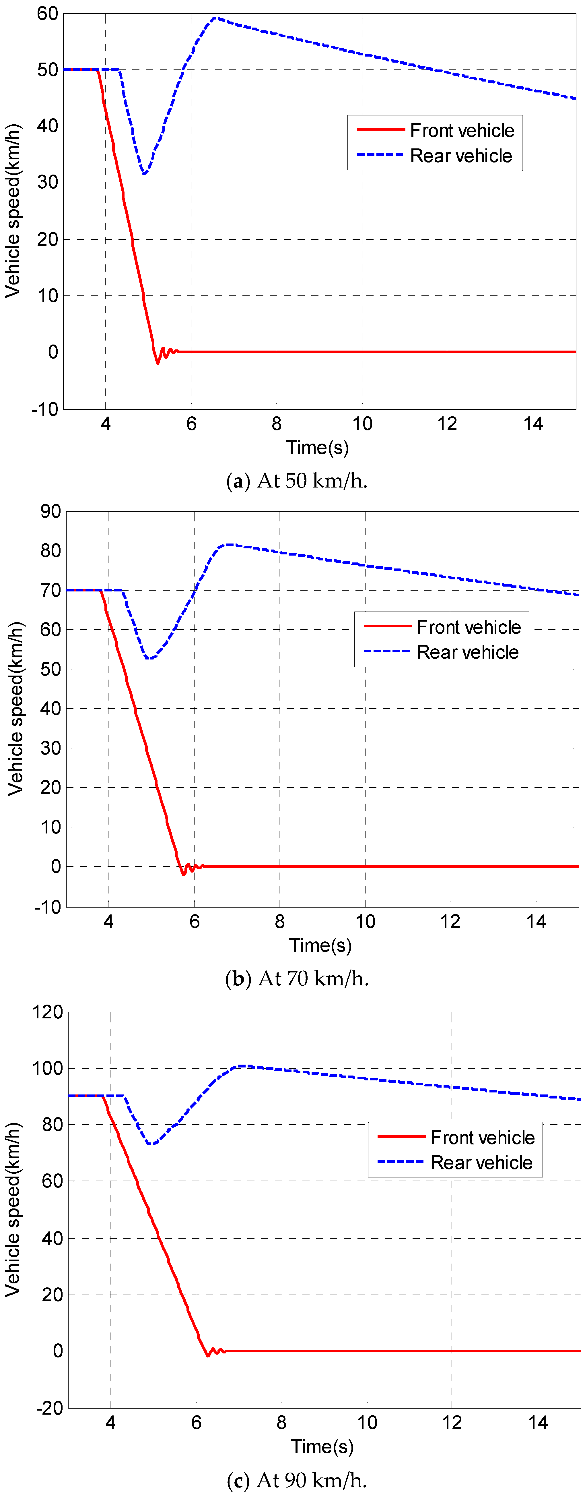
Figure 7 shows the evaluation results of the one-dimensional AEB at 50 km/h, 70 km/h, and 90 km/h, respectively. As can be seen in this figure, the proposed fuzzy braking has a better performance on stopping. In addition, the steering required to avoid two-dimensional collisions is built on the one-dimensional automatic brake. Basically, the AEB is activated when the distance is too short. When the distance reaches the preset value, the system will intervene to brake and avoid the collision. If the system suffers a disturbance from sudden accidents or intrusions to the brake intervention distance, it has to steer to avoid the obstacle. However, this function needs to consider the surroundings to determine the feasibility of intervention steering. If the surroundings allow for such maneuvers, the vehicle can automatically steer to avoid collisions.
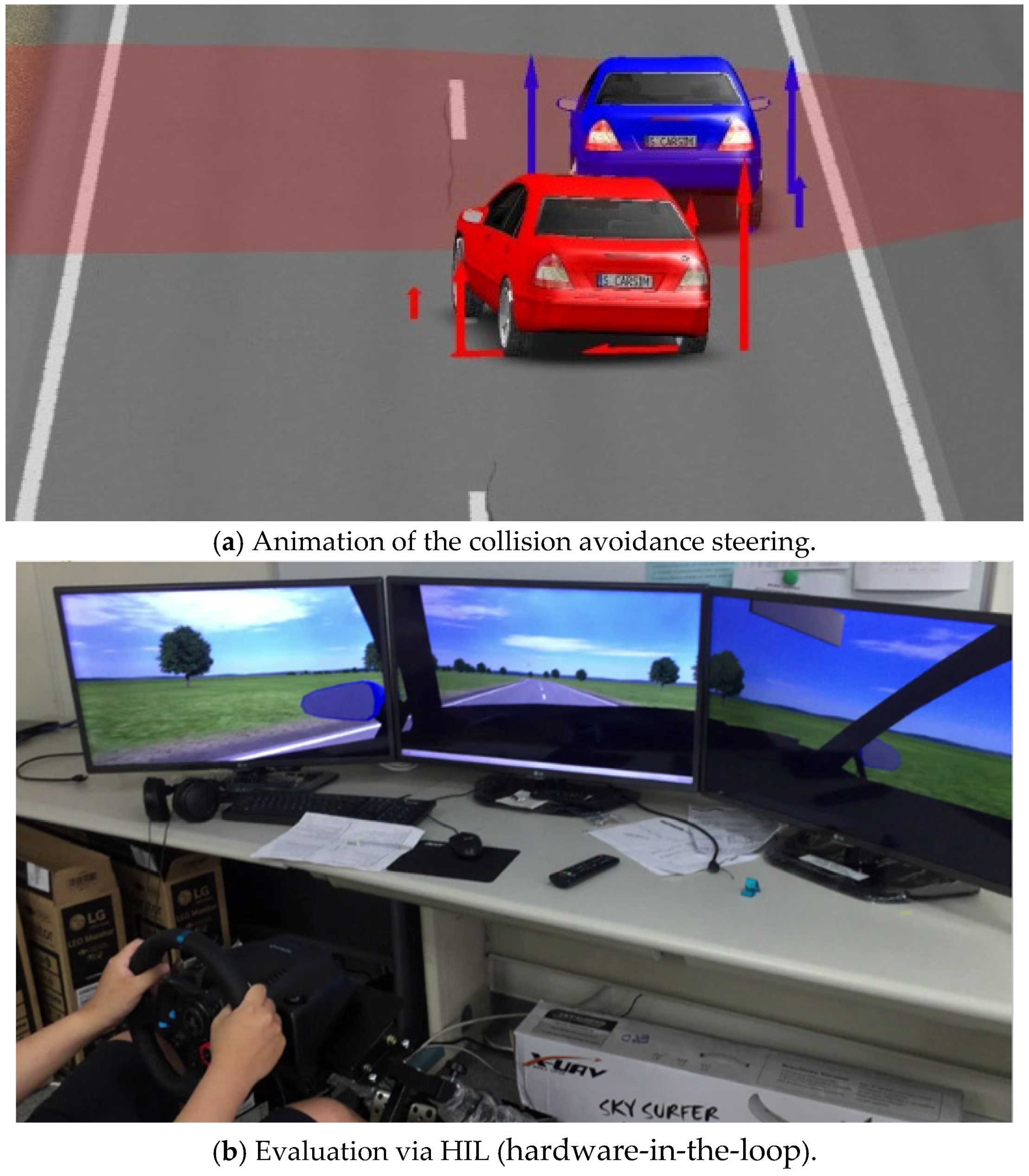
Likewise, the evaluation of the two-dimensional collision uses three velocities as the simulated conditions: 50 km/h, 70 km/h, and 90 km/h. When the distance is too short to initiate one-dimensional braking automatically, steering to avoid two-dimensional collisions will be executed, as shown in
Figure 8a, where two vehicles driving in the same lane simulate the steering to avoid two-dimensional collisions. This condition is simulated by two vehicles tracking each other. If the front vehicle suffers an accident or an emergency, the brake command will be given to both vehicles. The rear vehicle automatically initiates one-dimensional braking to prevent the collision; however, the condition is an unexpected accident, and thus it assesses the relative distance between the vehicles as being too short to avoid a collision by solely employing one-dimensional braking. Therefore, the system will start steering to avoid a collision by DCAC.
Figure 8b shows the photo taken from the experimental evaluation based on HIL where the user inputs commands via a real steering wheel and pedal. The virtual side from CarSim represents an animation for simulating the real driving experience.
Figure 9 shows the speed profile of the proposed steering.
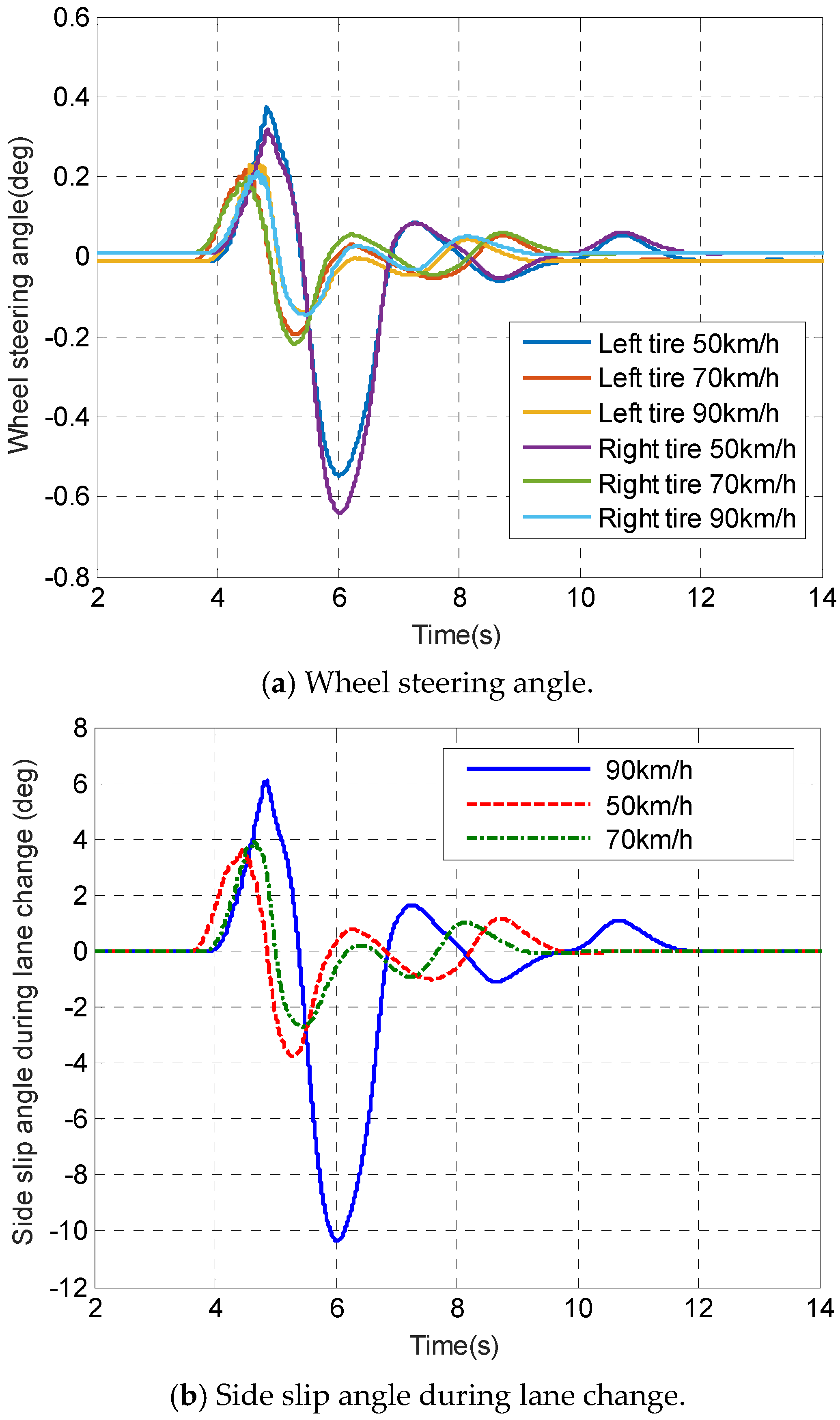
Figure 10a shows the wheel steering angle under the steering wheel rapidly turning 30° or 45°. Note that the reduction ratio of the steering angle between the operator and front wheels is 20:1.
Figure 10b demonstrates the dynamic stability by revealing the side slip angle during the lane change. As can be seen in this figure, the system stability is dominated by ESC when the DCAC is activated.


 ,
, 


