An Optimal Fuzzy PID Controller Design Based on Conventional PID Control and Nonlinear Factors


Department of Electrical Engineering, Southern Taiwan University of Science and Technology, 1, Nan-Tai St., Yongkang District, Tainan City 71005, Taiwan
*
Author to whom correspondence should be addressed.
Appl. Sci. 2019, 9(6), 1224; https://0-doi-org.brum.beds.ac.uk/10.3390/app9061224
Submission received: 3 February 2019
/
Revised: 8 March 2019
/
Accepted: 20 March 2019
/
Published: 23 March 2019
Abstract
:This paper proposes an optimal fuzzy proportional–integral–derivative (PID) controller design based on conventional PID control and nonlinear factors. With the equivalence between fuzzy logic controllers (FLCs) and conventional PID controllers, a conventional PID controller design can be rapidly transformed into an equivalent FLC by defining the operating ranges of the input/output of the controller. The proposed nonlinear factors can further tune the nonlinearity of the membership functions (MFs) distributed in the operating ranges. In this manner, a fuzzy PID controller can be developed with less parameters and optimized by using the genetic algorithm (GA). In addition, the aforementioned equivalent FLC can act as one individual in the initial population of GA, and significantly enhances the GA efficiency. Simulation results demonstrate the feasibility of this technique. This resulted in an optimal fuzzy PID controller design with only eight parameters with a concise controller structure, and most importantly, the optimal fuzzy PID controller design is now more systematic.
1. Introduction
The well-known proportional–integral–derivative (PID) controllers are still widely employed in industrial process control even though many kinds of control theories have been developed. The popularity of a PID controller can be attributed to its good performance and functional simplicity. The three-mode controller contains a proportional (P), an integral (I), and a derivative (D) term to make a system yield a desirable response in settling time, steady-state error, and overshoot. An engineer can efficiently tune the three gains through experience or some simple principles, such as the classical tuning rules proposed by Ziegler-Nichols [1]. Moreover, a simplified PI or PD controller is also popular for a multitude of practical applications.
A fuzzy logic controller (FLC) is based on fuzzy rules and fuzzy inference. The fuzzy rules can reflect human experience or knowledge, and exhibit nonlinearity to control more complex plants, which can be linear or nonlinear. Like conventional PI or PD controllers, FLCs also have PI-type or PD-type controllers. Essentially, a FLC design includes the type of FLC, the number and shape of membership functions (MFs), and the fuzzy rules [2]. The genetic algorithm (GA) is employed to determine the optimal parameters of a system. Since the design techniques of conventional linear PID controllers have matured, it is advantageous to use the GA to optimize fuzzy PID controller design. Researchers have introduced an analytical design for an optimal fuzzy PID controller [3], which has a simple structure, but uses complicated procedures. Another optimal fuzzy PID controller combining a fuzzy PI controller with a fuzzy D controller was proposed [4], but this device is actually a conventional PID controller with an adaptive control capability with complicated analytic formulas. An optimal fuzzy PID controller can also be built by combining a fuzzy PI controller and a fuzzy PD controller in parallelism [5] with optimal tuning of scaling factors and MFs. The conventional PID controller can also be directly put in the optimal design for fuzzy controllers [6], where the PID control is the master controller, and the fuzzy control is the slave control to enhance the master one.
The controller structure should be the primary consideration for a fuzzy PID controller design. As for the fuzzy control rules, in principle, they should follow conventional PID control. Then the problem of tuning the MFs in order to improve system performance must be solved [7]. The shape of MFs can be defined by chromosome bits and optimized by the GA [8,9] to improve the system responses, such as speed and precision of control [9,10]. On the other hand, each fuzzy variable MF is usually set to a symmetrical shape. The adjustment of a MF from symmetrical [11] to asymmetrical can also obtain improvements in system performance [12]. Moreover, some researchers use scaling factors to normalize the operating ranges and tune scaling factors to finish optimization [13]. In this paper, we choose to tune the operating ranges, which are important parameters for defining the equivalent FLC from a conventional PID controller.
In recent decades, many evolutionary algorithms have been developed, such as the particle swarm algorithm (PSO), cuckoo search (CS), and so on. Evolutionary programming (EP) claims that the traditional GA will not only have a premature convergence, but may also be trapped in the local optima. A fuzzy PID controller design using a novel PSO-EP based hybrid algorithm has been found in [14]. Furthermore, it is shown that a FLC + EP based PID controller provides a more rapid response than a FLC + GA based PID controller [15]. In this paper, we will still apply GA, and give each optimized parameter its own crossover point in the GA process to enhance the GA’s efficiency.
As most optimal fuzzy PID controller designs with complex structures or a large number of tuning parameters, this study developed an optimal fuzzy PID controller with less parameters and a concise controller structure. Based on our previous work, the equivalence between fuzzy PID controllers and conventional PID controllers is shown in [16]. Nonlinear factors are further proposed to represent the nonlinearity of the MFs distributed in the operating ranges. For each MF itself, it will exhibit an asymmetrical shape. In the proposed optimal fuzzy PID controller, there will be only a total of eight adjusted parameters. Moreover, if a conventional PID controller design can be obtained in advance, an equivalent FLC in the initial GA design can be used and this can potentially speed up the optimization process. Pelusi previously researched designing optimal control systems through GA and neuro-fuzzy techniques [17,18,19], and the results can be utilized as a benchmark to compare with the proposed design. Furthermore, the proposed optimal fuzzy PID controller is also applied to the motor control system [20], and the simulation results indicate speed control with good performance and the capability of disturbance rejection [21].
2. The Proposed Optimal Fuzzy PID Controller Design
The conventional PID controllers have been widely applied in industrial applications. The common equation is expressed as follows:
where the controller provides a proportional term, an integration term, and a derivative term. In the next section, we will describe the proposed optimal fuzzy PID controller design.
2.1. The Equivalent FLC from a Conventional PID Controller
For a conventional PID controller in Equation (1), the output and the three inputs , , and can be thought of as fuzzy variables in the FLC design. It is assumed that the operating ranges for , , , and are , , , and , respectively. In this subsection, some important results from our previous work [16] on the equivalence between fuzzy PID controllers and conventional PID controllers are excerpted to clarify the parameter definitions and notations.
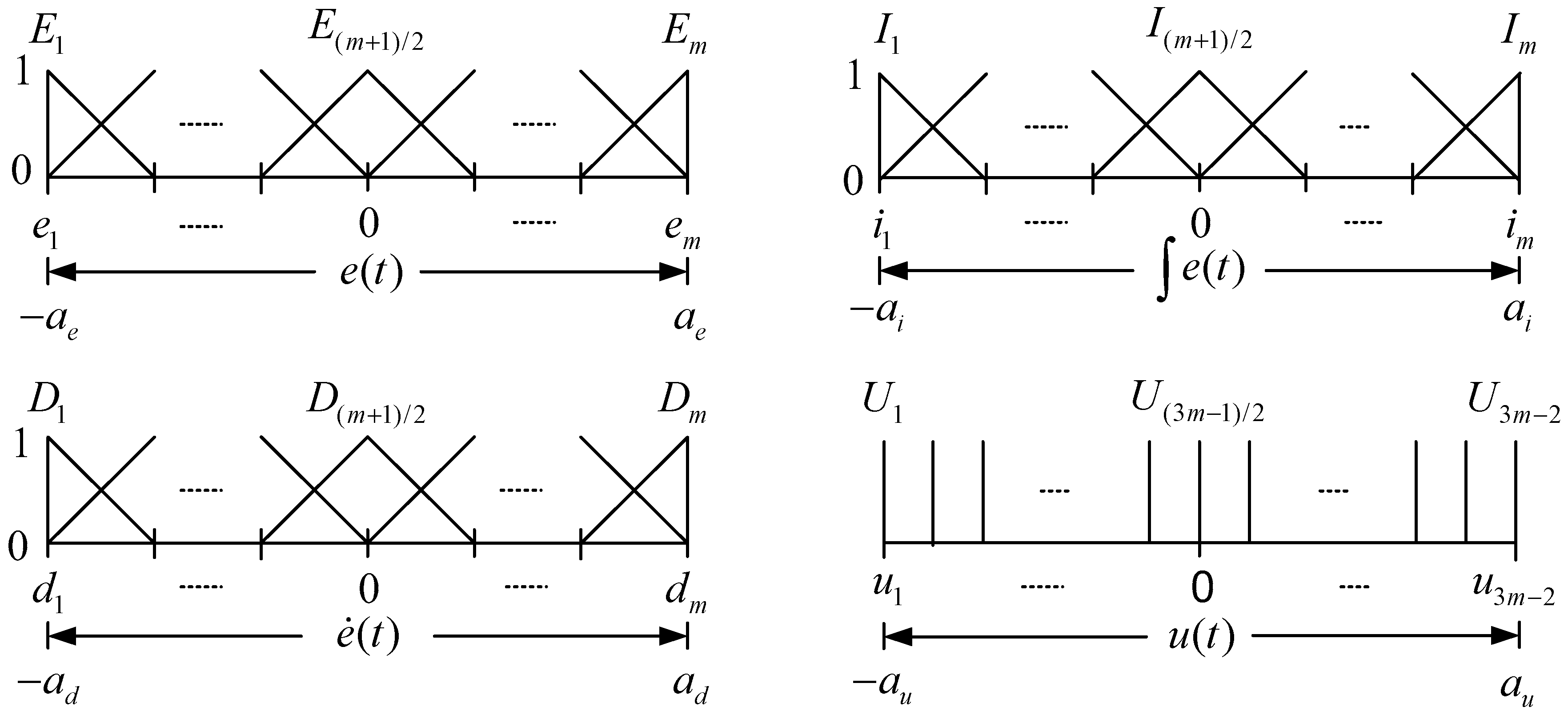
For input fuzzy variables , , and , each variable is represented by equally-spaced and triangular-shaped fuzzy sets, as shown in Figure 1. As for the output fuzzy variable , it is fuzzified by singleton MFs.
With the overall fuzzy rules represented by the sliced cube fuzzy associative memory (FAM), as shown in Figure 2, and each fuzzy rule defined as:
and the crisp output of the corresponding equivalent fuzzy logic controller is given by:
which implies a linear PID controller with:
We can find that Equation (4) has no relation with , and it is worth mentioning that the fuzzy inference and defuzzification processes should be limited to some specific operations [16]. Moreover, for the equivalent fuzzy PID Controller corresponding to a conventional PID controller, there are four parameters in all for tuning.
2.2. The Nonlinear Factor for Tuning MFs
In the previous subsection, the fuzzy sets representing input/output the fuzzy variables , , , and are equally-spaced, which is one of the reasons the results show a linear FLC. To exhibit the nonlinearity of a FLC, we proposed a nonlinear factor to tune MFs. Without losing its generality, let us take fuzzy variables and as an example. To illustrate the concept of nonlinear factor , is supposed to have = 7 fuzzy sets, and has = 19 fuzzy singletons, as shown in Figure 3. It is noted that the variable should be an odd number. In this paper, we use , , to represent the center of fuzzy sets or . The nonlinear factor is defined as:
It can be observed that the nonlinear factor represents the center distance ratio of the MFs before and after.
In Figure 3a, it is the linear case with nonlinear factor = 1. Figure 3b shows the case of < 1, where the closer the MF is to the zero, the wider the MF will be. On the contrary, if > 1, the closer MF to the zero will have a narrower shape, as shown in Figure 3c. With the definition of nonlinear factors, each MF itself can exhibit an asymmetrical shape and influence the system response.
From Equation (4) in Section 2.1, we get four parameters for tuning a linear FLC. Adding the nonlinear factor for each fuzzy variable in this subsection, there will be a total of eight parameters, , which need to be adjusted for an optimal fuzzy PID controller design.
2.3. The Efficient Genetic Algorithm
The GA is employed to find the optimal parameter set for a fuzzy PID controller. Basically, the GA includes some major components, such as encoding schemes, fitness evaluations, parent selection, crossover operators, and a mutation operator. This study applied binary coding and adopted the integrated absolute error (IAE) as the performance index [22], shown in Equation (6):
The fitness value will be the inverse value of the performance index, i.e., the smaller absolute sum of errors will obtain a larger fitness value.
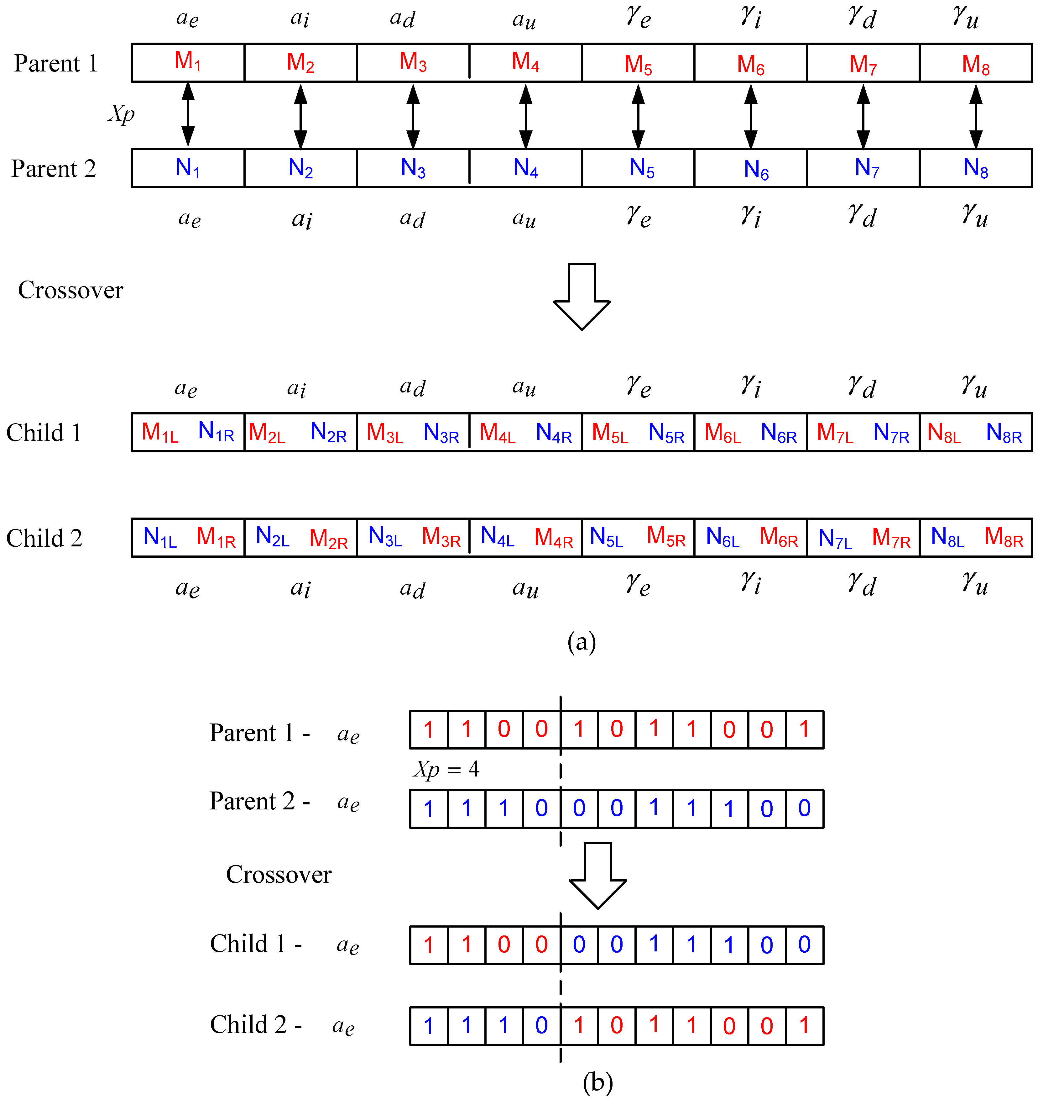
In this paper, we hope to enhance the GA efficiency, and discuss the crossover operation in GA computation. In some GA codes, the bits of different parameters will be concatenated into a large long string of bits. Afterwards, the crossover operation was done with only one crossover point. This will simplify the programming considerably, but may reduce GA efficiency due to the possible damage to good genes. In the proposed improved scheme, each parameter has its own crossover point, as illustrated in Figure 4. In this manner, good genes will not be easily destroyed by the crossover operation. Moreover, we will increase genetic diversity by enlarging the mutation rate. Simulation results show an efficient GA for optimal fuzzy PID controller design.
3. Simulation Results
This section evaluates the performance of the proposed optimal fuzzy PID controller by considering a two-order plant and motor control systems. The simulation is verified by use of Matlab/Simulation.
Simulation 1: A Two-Order Plant
A two-order controlled plant is shown below with transfer function [19]:
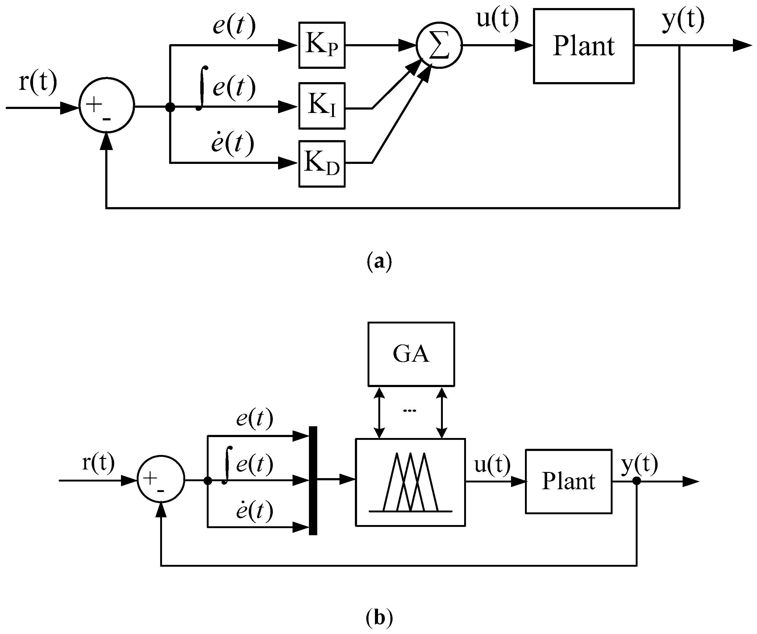
First, the unit feedback control structure is adopted, as shown in Figure 5. A preliminary conventional PID controller design with , , and can be obtained through some basic traditional techniques. Experiments to verify the proposed design approach can be seen in the following section.
Subsequently, we built the equivalent FLC for the above conventional PID controller design through the procedure shown below, which will satisfy Equation (4).
- is set as , which is the range for .
- is set as to satisfy .
- is set as to satisfy .
- is set as to satisfy .
The parameter is set as 5, resulting in 5 fuzzy sets for each input variable of the FLC. Figure 6 shows the settings of all the MFs in the Matlab environment. The linearity of the equivalent fuzzy PID controller can be verified by the control surface view shown in Figure 7, which is similar to the plan surface shown in [23]. The resulting equivalent fuzzy PID controller has almost the same system response as the conventional PID controller.
With the conventional PID controller design and the corresponding equivalent FLC, we finally have a basic understanding about the operating ranges of fuzzy I/O variables for a FLC. We can then add additional nonlinear factors and enlarge the operating ranges to find the optimal fuzzy PID controller through GA.
For the GA optimization, we use an 11-bit binary coding for each variable, and each generation contains 20 individuals. The search domains are confined to , , , and .
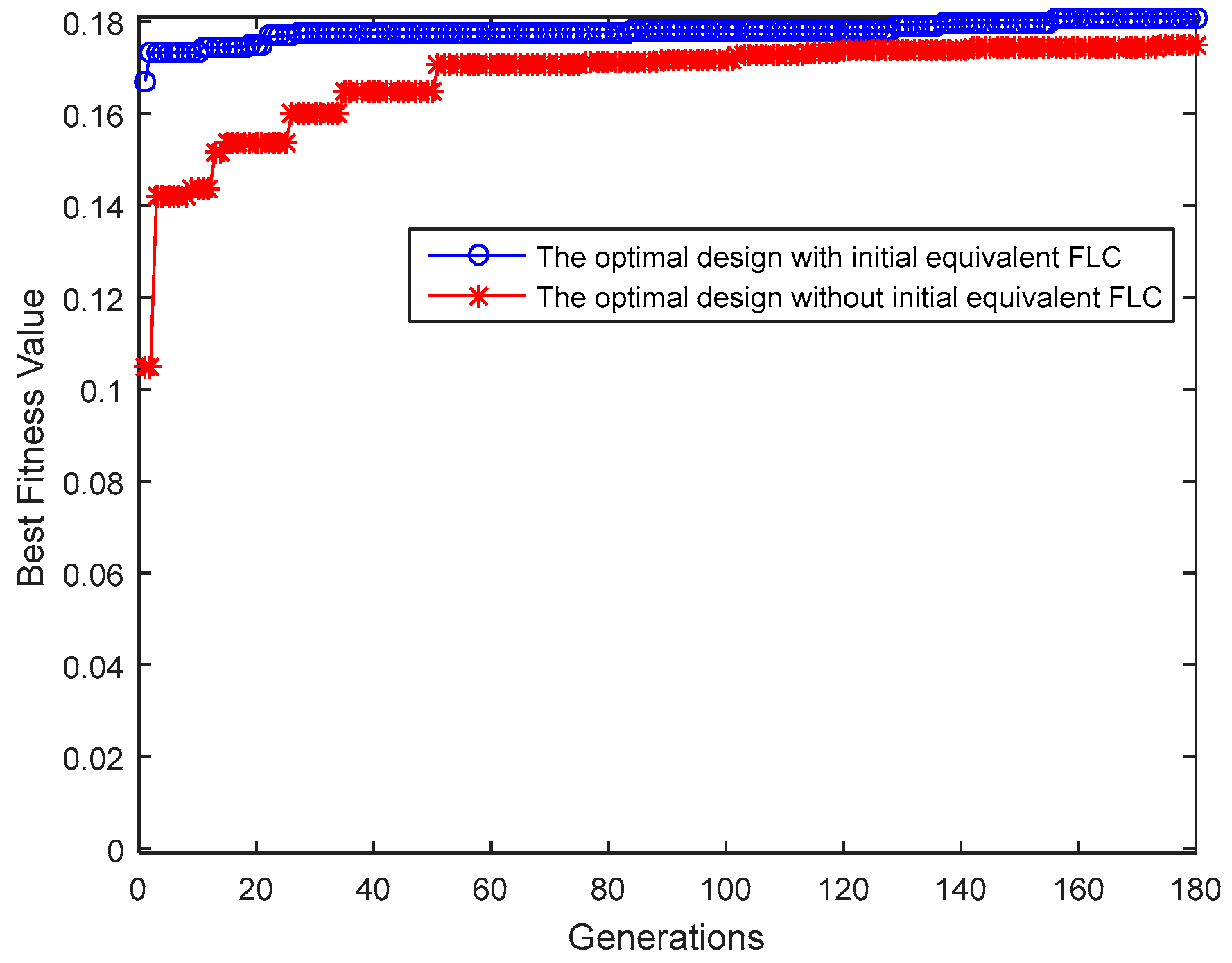
Moreover, the mutation rate is set as 0.1, and the elitism is applied to keep the best two individuals across generations. It is required to initialize a population with randomly generated individuals and evaluate the fitness value of each individual for the first step of GA. In this stage, our first attempt is taking the above equivalent FLC design, = [1.33, 0.266, 44.33, 199.5, 1, 1, 1, 1], as one individual in the population of the first generation. Figure 8 shows the performance of GAs across generations, where the optimal design with initial equivalent FLC may yield faster convergence with higher quality than the optimal design without initial equivalent FLC.
The step responses with the conventional PID controller (, , ) and the proposed optimal fuzzy PID controller (with initial equivalent FLC) are shown in Figure 9. The resulting eight optimized parameters are shown in Table 1. Furthermore, Table 2 summarizes the response performance, including the rise time (Tr), the settling time (Ts), the percentage overshoot (P.O.), and the steady-state error (Ess), of Pelusi’s GNFC optimized controller [19] and the proposed optimal fuzzy PID controller. Pelusi has provided many kinds of controllers, such as the genetic fuzzy controller (GFC), the neuro fuzzy controller (NFC), and the genetic neuro fuzzy controller (GNFC), but the GNFC has the best performance. Compared with Pelusi’s design, the proposed optimal FPID has smaller Tr and Ts, but a very small overshoot occurred at peak time t = 0.08 s with amplitude 1.0173, as shown in Figure 9. On the other hand, Pelusi’s GNFC controller belongs to a PD-type FLC, so Ess cannot be eliminated.
Figure 10 shows the MFs of the fuzzy I/O variables in the proposed optimal fuzzy PID controller, and the control surface view under is shown in Figure 11.
Simulation 2: DC Motor Speed Control
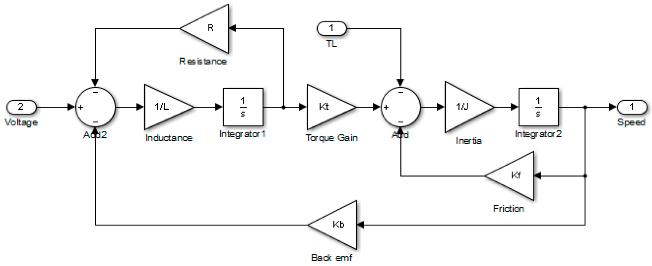
High-performance motor drives are very important in many industrial applications. Based on the design procedure in Simulation 1, a separately excited dc motor with the physical parameters listed in Table 3 is used as the controlled plant [20], and Figure 12 shows the constructed model in Simulink.
This is a speed control problem with the desired speed at 1200 rpm [20]. The control structure is shown in Figure 13 for both the PID controller and the proposed optimal fuzzy PID controller. The resulting speed responses of the initial conventional PID controller design with , , and , and the proposed optimal fuzzy PID controller are shown in Figure 14. The search domains of the operating ranges for this case are confined to , , , , and .
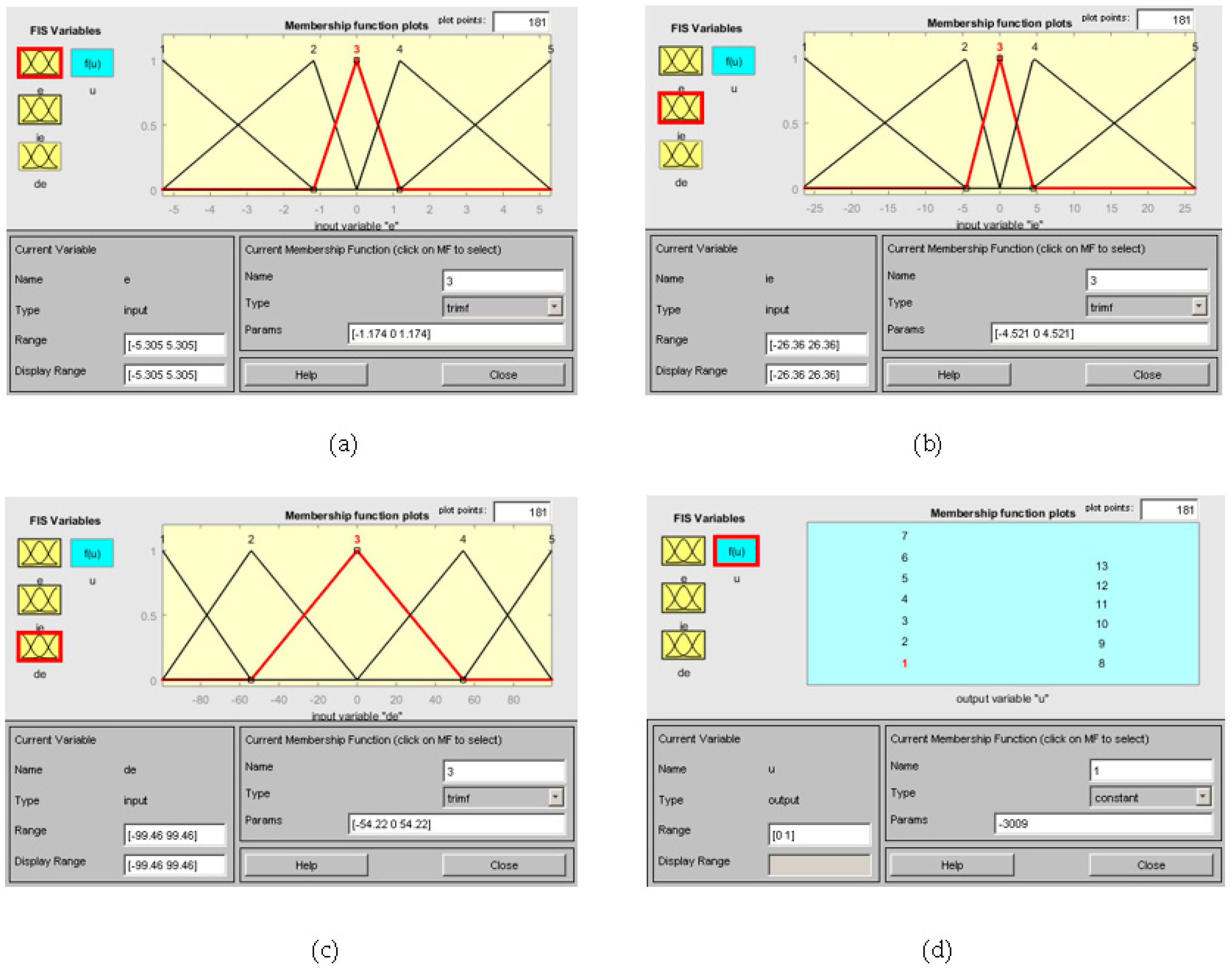
The resulting eight optimized parameters are shown in Table 4, and Table 5 summarizes some response parameters of Singh’s optimized fuzzy-GA controller [20] and the proposed optimal fuzzy PID controller. It shows that the proposed design has smaller Tr and Ts than Singh’s design. Finally, Figure 15 shows all the resulting MFs of the fuzzy I/O variables.
Simulation 3: DC Motor Speed Control with Load Disturbance
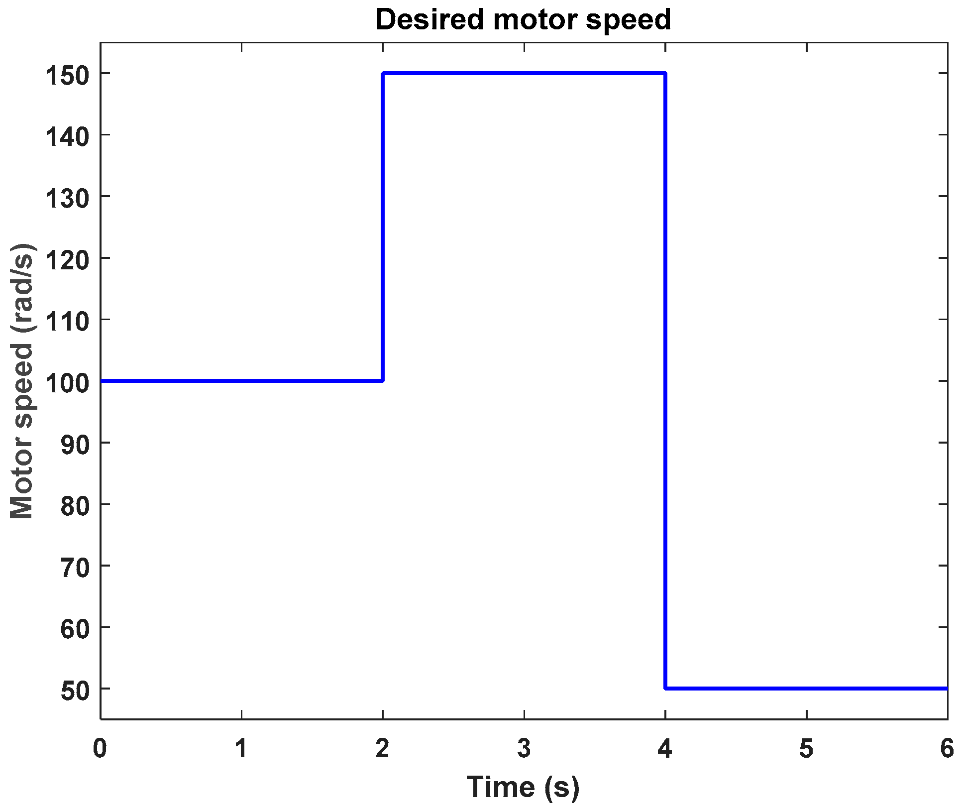
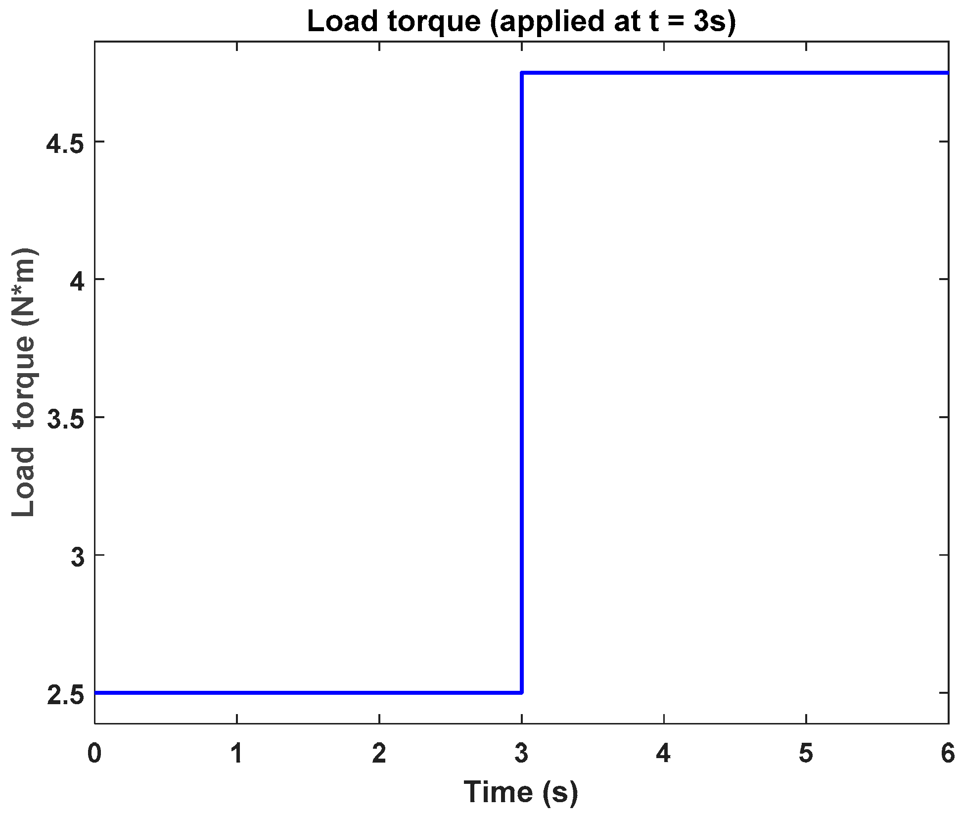
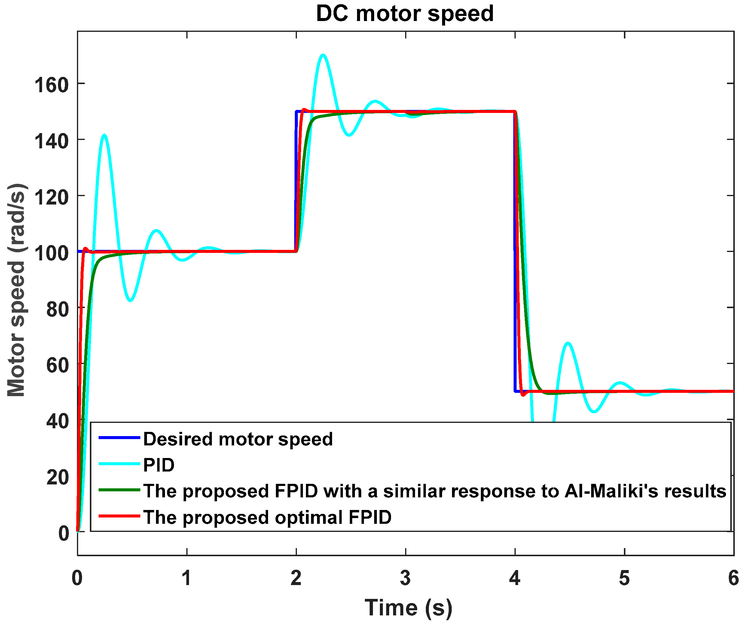
To further verify the feasibility and disturbance rejection capability of the proposed design, a DC motor speed control example with load disturbance [21] is adopted. Table 6 shows the DC motor parameters, and Figure 16 and Figure 17 illustrate the desired speed command and load disturbance at t = 3 s, respectively.
In this case, the sample-and-hold unit and the zero-order hold unit, which can be used to model A/D (analog-to-digital) and D/A (digital-to-analog) converters, are added to make a discretized FLC, as shown in Figure 18. It must be noted that the gain (K) in the “discrete-time integrator” and “discrete derivative” is set as 1 [16]. The system input and the resulting responses are shown in Figure 19, with sampling period ts set as 0.1 ms. The system responses in Figure 19 include the initial conventional PID controller design ( = 0.42, = 25.127, = 0.012), and the proposed optimal fuzzy PID controller design. Furthermore, since we cannot obtain the response waveform of Al-Maliki’s design [21], we run a similar response to Al-Maliki’s design by the proposed FPID.
Table 7 shows the eight optimized parameters of the proposed FPID design. The search domains of the operating ranges are confined to , , , , and . Then the performance comparison between Al-Maliki’s Fuzzy PID with KF (Kalman Filter) [21] and the proposed optimal FPID is summarized in Table 8. Simulation results demonstrate that the proposed optimal FPID has smaller Tr and Ts than Al-Maliki’s design, but has a larger overshoot. Furthermore, the proposed design has good performance in disturbance rejection.
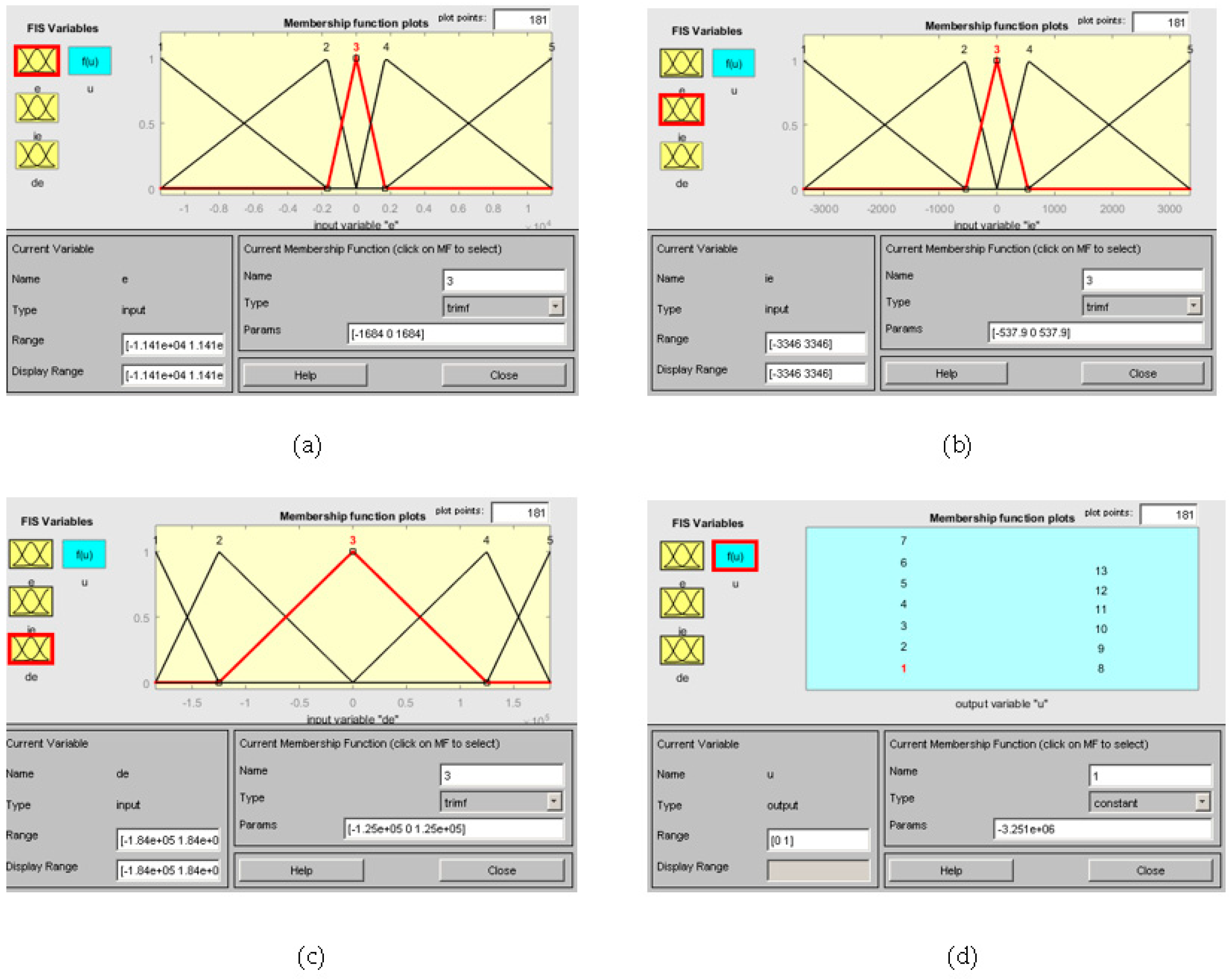
Finally, Figure 20 shows all the resulting MFs of the fuzzy I/O variables of the proposed optimal FPID, and the control surface view under is shown in Figure 21.
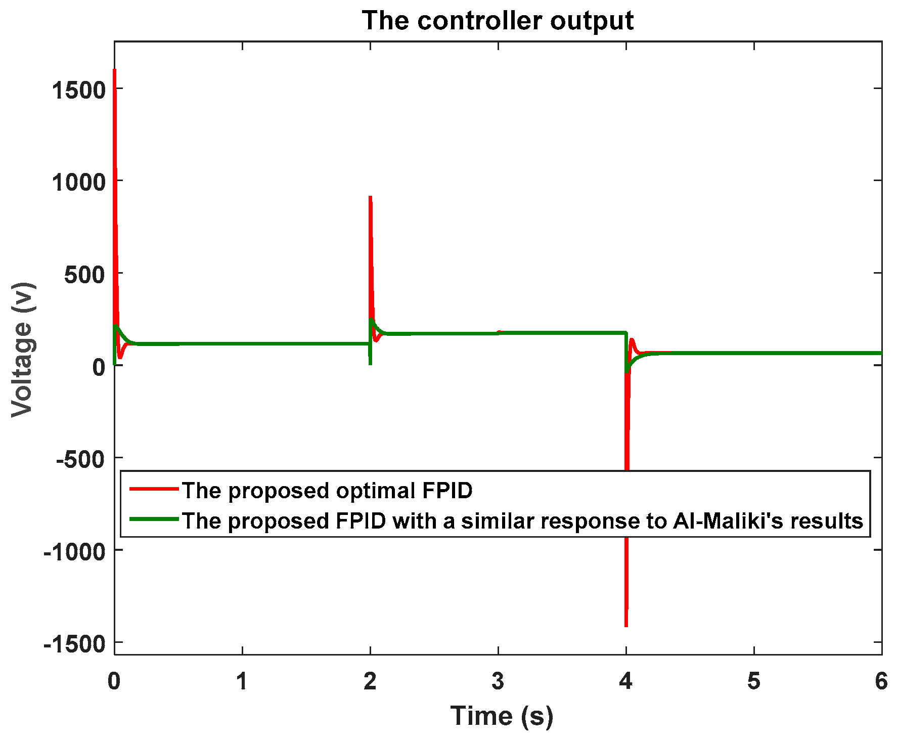
There is another main reason for us to run a system response which is similar to Al-Maliki’s design [21], as shown in Figure 19. As we also hope to compare the responses of the controller outputs, which will indicate the power consumption of the implemented controllers, and this is very important to help us understand the transient behaviors of the system. For a separately excited DC motor, the speed is controlled by varying the source voltage to armature. Figure 22 shows the controller outputs of the proposed optimal FPID and the proposed FPID with similar response to Al-Maliki’s design. The controller output of the proposed optimal FPID has a higher peak than Al-Maliki’s design.
To summarize of the above simulation examples, the proposed optimal fuzzy PID controller has quicker responses with smaller rising time and settling time. However, we still cannot claim that the proposed optimal FPID has outperformed other methods. In order to compare it with other approaches, we used the same IAE performance index, shown in Equation (6), but it is not practical to only consider the error signal without considering the energy or the power consumption of the controller output. The proposed optimal FPID design features a simple controller structure and a straightforward design approach based on conventional PID control and only eight nonlinear factors. Table 9 shows comparisons with the number of tuning parameters for different controllers.
4. Conclusions
Based on the equivalence between fuzzy PID controllers and conventional PID controllers, this paper proposed an optimal fuzzy PID controller design with each fuzzy variable’s MFs tuned by a nonlinear factor. Firstly, for a controlled plant, one can make a preliminary conventional PID controller design by some traditional techniques. Then the conventional PID controller design can be transformed into an equivalent FLC with four parameters defining the operating ranges of the I/Os. Subsequently, for each fuzzy I/O variable, one nonlinear factor is used for tuning the nonlinearity of MFs. Thus, there will be a total of eight parameters needed to be optimized by GA for an optimal fuzzy PID controller. To enhance the GA efficiency, each parameter must be given a crossover point. Finally, we set the aforementioned equivalent FLC to be one individual in the first generation of GA. This can yield quick and global convergence. In fact, we also found that in some simulations it made no significant difference if we did not take the equivalent FLC to act as one individual in the initial population of GA. This implies that the GA programming in this paper is really efficient. In conclusion, the proposed design approach makes an optimal fuzzy PID controller design more straightforward, and the controller structure more concise. This is quite advantageous for designers because they will have a clearer concept about the operating ranges of fuzzy I/O variables. As a result, we can now simply and appropriately increase the searching space for the optimal fuzzy PID controller design.
Author Contributions
J.-S.C. and C.-T.C. developed the methodology and drafted the manuscript. Moreover, N.S. implemented the Matlab/Simulink simulations, and C.-J.W. verified the results. The authors approved the final manuscript.
Funding
This research was funded by the Ministry of Science and Technology, Taiwan, under Grant no. MOST 106-2221-E-218-001-MY2. And the APC was funded by the Ministry of Science and Technology.
Acknowledgments
This work is supported by the Ministry of Science and Technology, Taiwan, under Grant no. MOST 106-2221-E-218-001-MY2. Furthermore, Nana Sutarna, one of the authors, is the lecturer of Jakarta State Polytechnic and studies in PhD program of Southern Taiwan University of Science and Technology (STUST) with scholarship supported by DGHE (Directorate General of Higher Education (Indonesia)) and STUST.
Conflicts of Interest
The authors declare no conflict of interest.
References
- Ziegler, J.G.; Nichols, N.B. Optimum settings for automatic controllers. Trans. ASME 1942, 64, 759–765. [Google Scholar] [CrossRef]
- Yan, K.; Mo, H. Application of fuzzy control under time varying universe in unmanned vehicles. In Proceedings of the 33rd Youth Academic Annual Conference of Chinese Association of Automation (YAC), Nanjing, China, 18–20 May 2018; pp. 439–444. [Google Scholar]
- Hu, B.G.; Mann, G.K.I.; Gosine, R.G. New methodology for analytical and optimal design of fuzzy PID controllers. IEEE Trans. Fuzzy Syst. 1999, 7, 521–539. [Google Scholar]
- Tang, K.S.; Man, K.F.; Chen, G.; Kwong, S. An optimal fuzzy PID controller. IEEE Trans. Ind. Electron. 2001, 48, 757–785. [Google Scholar] [CrossRef]
- Sebastiao, A.; Lucena, C.; Palm, L.; Cardoso, A.; Gil, P. Optimal tuning of scaling factors and membership functions for mamdani type PID Fuzzy controllers. In Proceedings of the IEEE International Conference on Control, Automation and Robotics, Singapore, 20–22 May 2015. [Google Scholar] [CrossRef]
- Zhou, Y.S.; Lai, L.Y. Optimal design for fuzzy controllers by genetic algorithms. IEEE Trans. Ind. Appl. 2000, 36, 93–97. [Google Scholar] [CrossRef]
- Salleh, Z.; Sulaiman, M.; Omar, R. Tuning fuzzy membership functions to improve performance of vector control induction drives. J. Telecommun. Electron. Comput. Eng. 2016, 8, 1–4. [Google Scholar]
- Kapetanovic, N.; Osmic, N.; Konjicija, S. Optimization of membership functions of Sugeno_Takagi fuzzy logic controllers with two inputs and one input using genetic algorithms. In Proceedings of the IEEE x International Symposium on Telecommunications (BIHTL), Sarajevo, Bosnia and Herzegovina, 27–29 October 2014. [Google Scholar]
- Pelusi, D.; Vazquez, L.; Diaz, D.; Mascella, R. Fuzzy algorithm control effectiveness on drum boiler simulated dynamics. In Proceedings of the 2013 36th International Conference on Telecommunications and Signal Processing (TSP), Rome, Italy, 2–4 July 2013; pp. 272–276. [Google Scholar]
- Ranjani, M.; Murugesan, P. Modeling of genetic algorithm based fuzzy logic controller for quasi-resonant converter fed drive. Int. J. Concept. Electr. Electron. Eng. 2013, 1, 25–29. [Google Scholar]
- Chen, S.M.; Chang, Y.C. A new weighted fuzzy rule interpolation method based on GA-based weights-learning techniques. In Proceedings of the Ninth International Conference on Machine Learning and Cybernetics, Qingdao, China, 11–14 July 2010; pp. 11–14. [Google Scholar]
- Al-Gizi, A.; Craciunescu, A.; Al-Chlaihawi, S. Improving the performance of PV system using genetically-tuned FLC based MPPT. In Proceedings of the 2017 International Conference on Optimization of Electrical and Electronic Equipment (OPTIM), Brasov, Romania, 25–27 May 2017; pp. 642–647. [Google Scholar]
- Gritli, W.; Gharsallaoui, H.; Benrejeb, M. PID-type fuzzy scaling factors tuning using genetic algorithm and simulink design optimization for electronic throttle valve. In Proceedings of the IEEE International Conference on Control, Design and Information Technologies (CoDIT), St. Julian’s, Malta, 6–8 April 2016; pp. 216–221. [Google Scholar]
- Chiou, J.S.; Liu, M.T. Numerical simulation for Fuzzy-PID controllers and helping EP reproduction with PSO hybrid algorithm. Simul. Model. Pract. Theory 2009, 17, 1555–1565. [Google Scholar] [CrossRef]
- Yau, H.T.; Yu, P.H.; Su, Y.H. Design and Implementation of optimal Fuzzy PID controller for DC servo motor. Appl. Math. Inf. Sci. 2014, 8, 231–237. [Google Scholar] [CrossRef]
- Chao, C.T.; Sutarna, N.; Chiou, J.S.; Wang, C.J. Equivalence between Fuzzy PID controllers and conventional PID controllers. Appl. Sci. 2017, 7, 513. [Google Scholar] [CrossRef]
- Pelusi, D. Optimization of fuzzy logic controller using genetic algorithms. In Proceedings of the IEEE Third International Conference on Intelligent Human-Machine Systems and Cybernetics (IHMSC), Hangzhou, China, 26–27 August 2011; Volume 2, pp. 143–146. [Google Scholar] [CrossRef]
- Pelusi, D. Designing neural networks to improve timing performances of intelligent controllers. J. Discret. Math. Sci. Cryptogr. 2013, 16, 187–193. [Google Scholar] [CrossRef]
- Pelusi, D.; Mascella, R. Optimal control algorithms for second order systems. J. Comput. Sci. 2013, 9, 183–197. [Google Scholar] [CrossRef]
- Singh, A.R.; Giri, V.K. Design and analysis of DC motor speed control by GA based tuning of fuzzy logic controller. Int. J. Eng. Res. Technol. 2012, 1, 1–6. [Google Scholar]
- Al-Maliki, A.Y.; Iqbal, K. FLC-based PID controller tuning for sensorless speed control of DC motor. In Proceedings of the IEEE International Conference on Industrial Technology (ICIT), Lyon, France, 20–22 February 2018; pp. 169–174. [Google Scholar]
- Mirzal, A.; Yoshii, S.; Furukawa, M. PID parameters optimization by using genetic algorithm. ISTECS J. 2006, 8, 34–43. [Google Scholar]
- Pelusi, D.; Mascella, R.; Tallini, L.; Nayak, J.; Naik, B.; Abraham, A. Neural network and fuzzy system for the tuning of gravitational search algorithm parameters. Int. J. Expert Syst. Appl. 2018, 102, 234–244. [Google Scholar] [CrossRef]
Figure 1.
Graphical definition of MFs for fuzzy variables, , , , and .

Figure 2.
Sliced cube fuzzy associative memory (FAM) representation of the knowledge base.

Figure 3.
Different nonlinear factor for tuning MFs. (a) = 1; (b) < 1; and (c) > 1.

Figure 4.
Crossover operation: (a) all parameters; and (b) single parameter.

Figure 5.
The unit feedback control structure: (a) PID control; and (b) optimal fuzzy PID control.

Figure 6.
Membership functions for fuzzy variables: (a) ; (b) ; (c) ; and (d) in Matlab.

Figure 7.
The control surface view of the equivalent fuzzy PID controller ( = 0.266).

Figure 8.
Performance of GAs across generations: (a) with initial equivalent FLC; and (b) without initial equivalent FLC.
Figure 8.
Performance of GAs across generations: (a) with initial equivalent FLC; and (b) without initial equivalent FLC.

Figure 9.
The step responses: (blue) the conventional PID controller; and (red) the proposed optimal fuzzy PID controller.
Figure 9.
The step responses: (blue) the conventional PID controller; and (red) the proposed optimal fuzzy PID controller.

Figure 10.
Membership functions for fuzzy variables: (a) ; (b) ; (c) ; and (d) in Matlab.

Figure 11.
The control surface view of the proposed optimal fuzzy PID controller .

Figure 12.
The block diagram of the DC motor.

Figure 13.
The control system of the PID controller and the proposed optimal fuzzy PID controller.

Figure 14.
The motor speed control of the conventional PID controller and the proposed optimal fuzzy PID controller.
Figure 14.
The motor speed control of the conventional PID controller and the proposed optimal fuzzy PID controller.

Figure 15.
Membership functions for fuzzy variables: (a) ; (b) ; (c) ; and (d) in Matlab.

Figure 16.
Desired motor speed.

Figure 17.
Load torque as disturbance.

Figure 18.
The proposed FLC-controlled system in discrete form.

Figure 19.
The motor speed input and system responses.

Figure 20.
Membership functions for fuzzy variables: (a) ; (b) ; (c) ; and (d) in Matlab.

Figure 21.
The control surface view of the proposed optimal fuzzy PID controller .

Figure 22.
The controller outputs.


Table 1.
The eight optimized parameters.
| Optimized Operating Ranges | Optimized Nonlinear Factors | ||||||
|---|---|---|---|---|---|---|---|
| 5.3053 | 26.3556 | 99.4626 | 3009.3 | 4.1275 | 5.5227 | 0.8344 | 0.2872 |
Table 2.
Response performance of different controllers.
| Controller | Tr (s) 10–90% | P.O. (%) | Ess | |
|---|---|---|---|---|
| Pelusi’s GNFC [19] | 0.153 | 0.276 | 0 | 0.917 |
| The proposed optimal FPID | 0.047 | 0.059 | 1.73 | 0 |
Table 3.
DC motor parameters [20].
Table 3.
DC motor parameters [20].
| Parameter/Specification | Value | Unit |
|---|---|---|
| (Armature resistance) | 1 | Ohm |
| (Armature inductance) | 0.5 | H |
| (Rotor inertia) | 0.01 | Kg·m2 |
| (Back EMF constant) | 0.01 | Volt·s/rad |
| (Torque constant) | 0.01 | N·m/A |
| (Mechanical damping factor) | 0.1 | N·m·s/rad |
| Rated speed | 1200 | r.p.m |
Table 4.
The eight optimized parameters.
| Optimized Operating Ranges | Optimized Nonlinear Factors | ||||||
|---|---|---|---|---|---|---|---|
| 5061.1 | 12,946 | 122,030 | 3,556,400 | 2.7357 | 0.8036 | 0.6253 | 0.1661 |
Table 5.
Response performance of different controllers.
| Controller | Tr (s) 10–90% | P.O. (%) | |
|---|---|---|---|
| Singh’s Fuzzy GA controller [20] | 0.1 | 0.121 | 5.8466 |
| The proposed optimal FPID | 0.044 | 0.054 | 2.23 |
Table 6.
DC motor parameters [21].
Table 6.
DC motor parameters [21].
| Parameter/Specification | Value | Unit |
|---|---|---|
| (Armature resistance) | 2.25 | Ohm |
| (Armature inductance) | 4.65 × 10⁻² | H |
| (Rotor inertia) | 7 × 10⁻² | Kg·m2 |
| (Back EMF constant) | 1.1 | Volt·s/rad |
| (Torque constant) | 1.1 | N·m/A |
| (Mechanical damping factor) | 2 × 10⁻³ | N·m·s/rad |
Table 7.
The eight optimized parameters.
| Optimized Operating Ranges | Optimized Nonlinear Factors | |||||||
|---|---|---|---|---|---|---|---|---|
| The proposed optimal FPID | 11,412 | 3346.4 | 183,980 | 3,251,100 | 6.5110 | 5.9331 | 0.4719 | 2.5169 |
| The proposed FPID with a similar response to Al-Maliki’s results | 1000 | 137 | 117,000 | 264,180 | 2.3145 | 2.1590 | 5.9060 | 3.1692 |
Table 8.
Response performance of different controllers.
| Controller | Tr (s) 10–90% | P.O. (%) | |
|---|---|---|---|
| Al-Maliki’s FLC-PID with KF [21] | ~0.15 | 0.257 | 0.5 |
| The proposed optimal FPID | 0.0409 | 0.0516 | 1.38 |
| The proposed FPID with a similar response to Al-Maliki’s results | 0.14 | 0.254 | 0 |
© 2019 by the authors. Licensee MDPI, Basel, Switzerland. This article is an open access article distributed under the terms and conditions of the Creative Commons Attribution (CC BY) license (http://creativecommons.org/licenses/by/4.0/).
Share and Cite
MDPI and ACS Style
Chao, C.-T.; Sutarna, N.; Chiou, J.-S.; Wang, C.-J. An Optimal Fuzzy PID Controller Design Based on Conventional PID Control and Nonlinear Factors. Appl. Sci. 2019, 9, 1224. https://0-doi-org.brum.beds.ac.uk/10.3390/app9061224
AMA Style
Chao C-T, Sutarna N, Chiou J-S, Wang C-J. An Optimal Fuzzy PID Controller Design Based on Conventional PID Control and Nonlinear Factors. Applied Sciences. 2019; 9(6):1224. https://0-doi-org.brum.beds.ac.uk/10.3390/app9061224
Chicago/Turabian StyleChao, Chun-Tang, Nana Sutarna, Juing-Shian Chiou, and Chi-Jo Wang. 2019. "An Optimal Fuzzy PID Controller Design Based on Conventional PID Control and Nonlinear Factors" Applied Sciences 9, no. 6: 1224. https://0-doi-org.brum.beds.ac.uk/10.3390/app9061224
Note that from the first issue of 2016, this journal uses article numbers instead of page numbers. See further details here.