Article

High Temperature Corrosion Studies of a Zirconia Coating: Implications for Waste-to-Energy (WTE) Plants

1
Section for Mineralogy, Petrology and Geochemistry, Department for Earth and Environmental Sciences, Ludwig-Maximilians-Universität München, Theresienstrasse 41, 80333 Munich, Germany
2
Fraunhofer UMSICHT, An der Maxhütte 1, 92237 Sulzbach-Rosenberg, Germany
3
MARTIN GmbH für Umwelt- und Energietechnik, Leopoldstrasse 248, 80807 Munich, Germany
4
Zweckverband Müllverwertung Schwandorf, Alustrasse 7, 92421 Schwandorf, Germany
5
Deutsche Edelstahlwerke GmbH, Sonderwerkstoffe, Entwicklung und Innovation, Oberschlesienstrasse 16, 47807 Krefeld, Germany
6
Rohrwerk Maxhütte GmbH, Franz-Kunze-Straße 1, 92237 Sulzbach-Rosenberg, Germany
*
Author to whom correspondence should be addressed.
Submission received: 12 July 2016 / Revised: 10 August 2016 / Accepted: 22 August 2016 / Published: 25 August 2016

Abstract

:
Corrosion of functional parts within waste-to-energy (WTE) plants significantly reduces their efficiency with respect to maintenance costs. Currently, nickel-based alloy claddings, several millimeters thick, are the state of the art as anti-corrosion coating. Another approach is to utilize thermally sprayed multilayer coatings with a zirconia top-coat. Lab-scale experiments under simulated WTE plant conditions and in situ tests within a WTE plant revealed a partially reduced porosity of the zirconia top-coat after the experiments, enabling the coating to act as a barrier against aggressive gases. In a lab-scale experiment sample the pores are filled up with zirconia, while the pores of the in situ samples are filled up with newly formed metal (Cr, Ni, Fe) oxides.

1. Introduction

Corrosion attack of superheater steel tubes in waste-to-energy (WTE) plants has become a crucial problem in the last 50 years [1]. Great efforts have been made to understand the corrosion process and to develop corrosion-resistant tubing, or tube coatings, to withstand attack by aggressive gas species, such as chlorine and sulfur-containing compounds, produced by the combustion process [2,3,4,5]. Depending on the plant parameters (layout, steam parameters, etc.) and the composition of the fired materials, various corrosion-resistant materials have been investigated and utilized. In the last decades, the use of nickel-based superalloy claddings has found widespread application. In particular, Inconel 625 is a widely used material, due to its good corrosion resistance with lifetimes of up to 20 years [6,7,8,9]. With a thickness of several millimeters, these claddings are very cost intensive. Their application as thermal-sprayed coatings by atmospheric plasma spray (APS) or high velocity oxygen-fuel spray (HVOF) techniques, with thicknesses less than 1 mm, is not only favorable in terms of cost and time efficiency [10,11,12] but also for thermal efficiency for heat-exchanging devices. An alternative approach is to use APS-applied multilayer coatings as durable corrosion inhibitor materials. Corrosion tests within a WTE plant with internally cooled test probes (450 °C) of a steel tube (St 37.8/1.0345) as substrate material, coated with Inconel 625 as the bond-coat and yttria-stabilized zirconia (YSZ) as the top-coat, showed an improved corrosion resistance [13]. This material combination was placed in a WTE plant in a flue gas temperature range between 680 and 740 °C for 500 h (~21 days). Notably, a modified area of YSZ at the border between bond- and top-coat was observed, which exhibited significantly reduced porosity. This observation suggests a densification process of the YSZ ceramic and therefore better wear and corrosion resistance. It was assumed that this phenomenon was the result of the solvothermal transport of zirconium via a vapor flux. Therefore, it seemed possible to develop a protective layer for the underlying metallic substrate to improve its wear resistance and prevent further corrosion. In lab-scale experiments under simulated waste incineration conditions, this densification of the YSZ has been successfully reproduced [14,15,16,17]. Those experiments were conducted within a temperature range between 600 and 800 °C, utilizing a synthetic atmosphere of nitrogen (N2) with 2 vol.% gaseous hydrochloric acid (HCl). Additionally, a salt mixture of potassium and zinc chlorides and sulfates (KCl, ZnCl2, K2SO4, ZnSO4), together with YSZ powder was placed within the furnace. This treatment was intended to promote the formation of volatile zirconium chloride species, which would subsequently diffuse through open pores and cracks of the ceramic top-coat, and would recrystallize as zirconium oxide, starting from the bond-coat–top-coat interface outward. Various tests were performed to analyze the mechanical and thermal shock resistance of the modified samples. They evidenced an improved adhesive strength in-between the ceramic top-coat and the metallic bond-coat [14,15,17].
In general, zirconium is not a common element within the flue gas of a WTE plant. This raises the question how the densification process observed within the YSZ top-coat of prior lab-scale experiments can occur when the material was exposed to WTE plant conditions. Therefore, additional lab-scale experiments with YSZ-coated samples under a synthetic atmosphere of nitrogen, gaseous hydrochloric acid, and oxygen without additional zirconium introduced into the gas flow were performed. Furthermore, YSZ-coated test probes were placed within a WTE plant in order to examine the densification process under true operational conditions.

2. Materials and Methods

2.1. WTE Plant Test

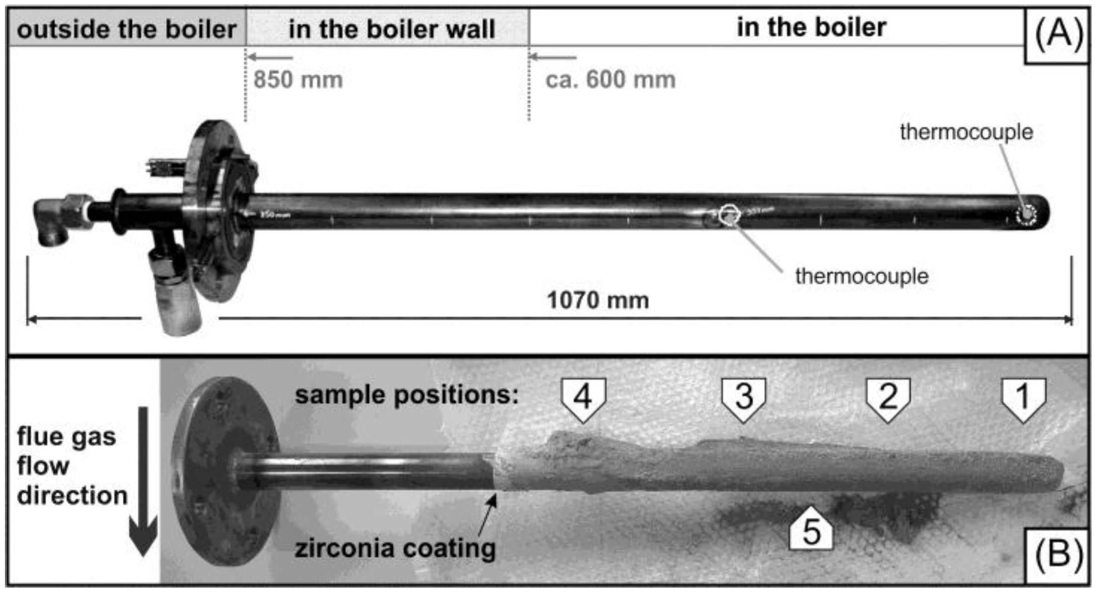
2.1.1. Sample Preparation

All parts of the heat exchanging system in WTE plants must fulfill boiler engineering requirements, e.g., seamless steel tubes to resist high steam pressures. Superheater components consist of seamless 1.0345-steel tubes, which are manufactured by the so-called Mannesmann- or pilgrim-rolling process. The original steel tube, referred to as substrate, was used as a test probe for in situ investigations (Figure 1A). In order to record the temperature history and to ensure a desired temperature profile they were equipped with thermocouples and a thermostat.
To activate the substrate surface for the following APS coating process, it was corundum-blasted and heated up to 150 °C [18]. The substrate was coated all the way around the tube with an APS-applied multilayer system, consisting of a metal bond-coat as inner layer, which is covered by a ceramic top-coat. The YSZ top-coat represents a high temperature-resistant outer layer of the system. The nickel-based bond-coat (Nibasit 625-P, Deutsche Edelstahlwerke (DEW), Krefeld, Germany) improves the corrosion stability, acts as an adhesive layer, and has to compensate stress-induced strains by different thermal expansion coefficients of the layers. The thicknesses of the multilayer coatings of different samples vary within the range of 300–500 µm.

2.1.2. Experimental Setting

The in situ tests were performed in the WTE plant Zweckverband Müllverwertung Schwandorf (ZMS) in Schwandorf, Bavaria, Germany, consisting of four separate combustion lines. The incinerator has a waste throughput of 12.5 t/h, operating at a live steam pressure of 72 bar and 410 °C. It uses a horizontal grate system to burn municipal and industrial solid waste. Three sample locations at the upper part of the second pass were prepared to accommodate test probes described above. This setup enables the simultaneous operation of three test probes under similar conditions. The test probes extend about 60 cm into the second pass of the incineration plant, facing the flue gas temperature of approximately 700 °C. Two sets of experiments were carried out (Table 1).

(1) In situ test at 700 °C

An uncooled test probe (TP 1) was placed for 14 days in the WTE plant at a flue gas temperature of 700 °C (±25 °C).

(2) In situ test at 450 °C

In order to simulate temperatures which are typically found in membrane walls and superheater tubes, three test probes (TP 2.1, 2.2, 2.3) were cooled by circulating compressed air, to achieve a temperature of 450 °C (±10 °C). These cooled test probes were placed in the WTE plant for 23 days.
As municipal solid waste is a highly heterogeneous fuel, slightly different chemical conditions of the flue gas in different in situ experiments should be considered. In general, the following concentrations of gaseous HCl and SO2 can be assumed (measured values are not available): HCl, 0.09 vol.%; SO2, 0.005 vol.%.

2.2. Lab-Scale Experiments

2.2.1. Sample Preparation

For lab-scale experiments, cylindrically shaped steel substrates (St 35.8/1.0345—2 cm diameter, 1 cm high) were used. The multilayer coating was applied by APS process. The multilayer system consists of a nickel-based bond-coat (Nibasit 625-P, DEW, Krefeld, Germany) (Table 2) and an YSZ top-coat (8 wt.% Y2O3 stabilized zirconia—GTV, Luckenbach, Germany). The thicknesses of bond- and top-coat are approximately 100 µm and 200 µm, respectively.

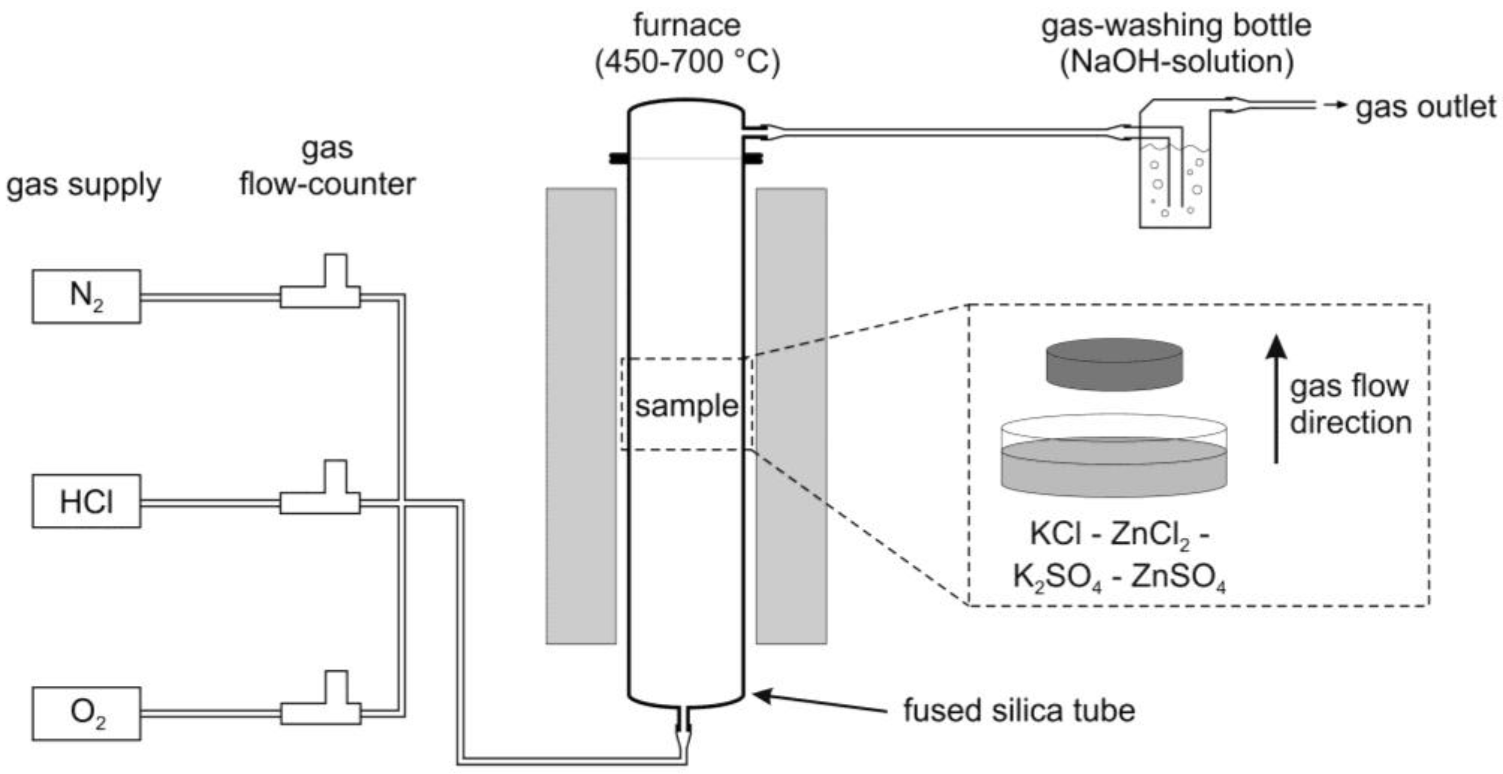
2.2.2. Experimental Setup

The sample was placed in a fused silica glass tube in a vertically mounted tube furnace (Figure 2). The samples LS 1 and LS 2 were exposed to high temperatures of 500 °C (LS 1) and 700 °C (LS 2) and an atmosphere of N2—2.1 vol.% HCl—0.9 vol.% O2. Additionally, an equimolar mixture of KCl, ZnCl2, K2SO4, and ZnSO4 was positioned in the gas flow (Table 1). The duration of each experiment was 2 days with a heating rate of 3 K/min; the cooling rate was lower. An untreated sample (LS 3) was used as a reference.

2.3. Characterization Methods

For the test probes, the flue gas-facing side (luv) and the face-away side of the flue gas (lee) were investigated separately. The uncooled test probe exposed an up to 3 cm thick layer of flue gas deposits on the surface, as shown in Figure 1B. These deposits were analyzed by X-ray fluorescent (XRF) and X-ray diffraction (XRD) analyses at different positions on the luv side (Figure 1B, position 1–4) and another on the opposite side (Figure 1B, position 5).
Porosity determination of in situ and lab-scale samples, element mappings, and energy dispersive X-ray (EDX) analyses were done with an electron-probe micro-analyzer (EPMA) (Cameca SX 100) equipped with a LaB6 cathode.
The chemical compositions of the flue gas deposits were determined by ED-XRF analyses (Philips, MagiX Pro). To determine the loss on ignition (LOI), the sample material was dried at 110 °C for >6 h and subsequently ignited at 1050 °C for >2 h. The major and minor elements were measured using glass beads prepared by fusion of 1 g of ignited sample powder and 9 g SPECTROMELT A12 (66% di-lithium tetraborate, 34% lithium metaborate) in a Panalytical Eagon 2 furnace fusion system at 1150 °C. The percentage relative standard deviation (%RSD) for element concentrations >500 ppm is ~2.4%, and ~7.5% for values <500 ppm.
For XRD analyses the flue gas deposits were powdered by manual grinding in an agate mortar and placed on a SiO2 zero background sample holder. Measurement was done one a GE X-ray diffractometer (XRD 3003 TT) by using Cu Kα1 radiation. The measured 2 theta range was 10°–100° in Bragg-Brentano geometry.
For EPMA analyses, the samples were cut perpendicular to the coating layer and embedded in epoxy. Polishing was done with diamond paste of decreasing grain size down to 1 µm to obtain a flat surface. Porosity was determined by defining a threshold in visible light images for in situ samples and in backscattered-electron (BSE) images for lab-scale samples, using the ImageJ software (vers. 1.50e). The element distribution within the samples was analyzed by qualitative element mappings. An accelerating voltage of 15 keV at 40 nA was used. The step size was chosen to be 1 µm per pixel.

3. Results and Discussion

3.1. In Situ Test in the WTE Plant

EPMA analyses (BSE images and element mappings) of the multilayer were carried out. For samples from positions 1–4 (luv) XRD and XRF analyses were carried out, and for the sample from position 5 (lee) only XRD analyses were carried out (Table 1).

3.1.1. In Situ Test at 700 °C
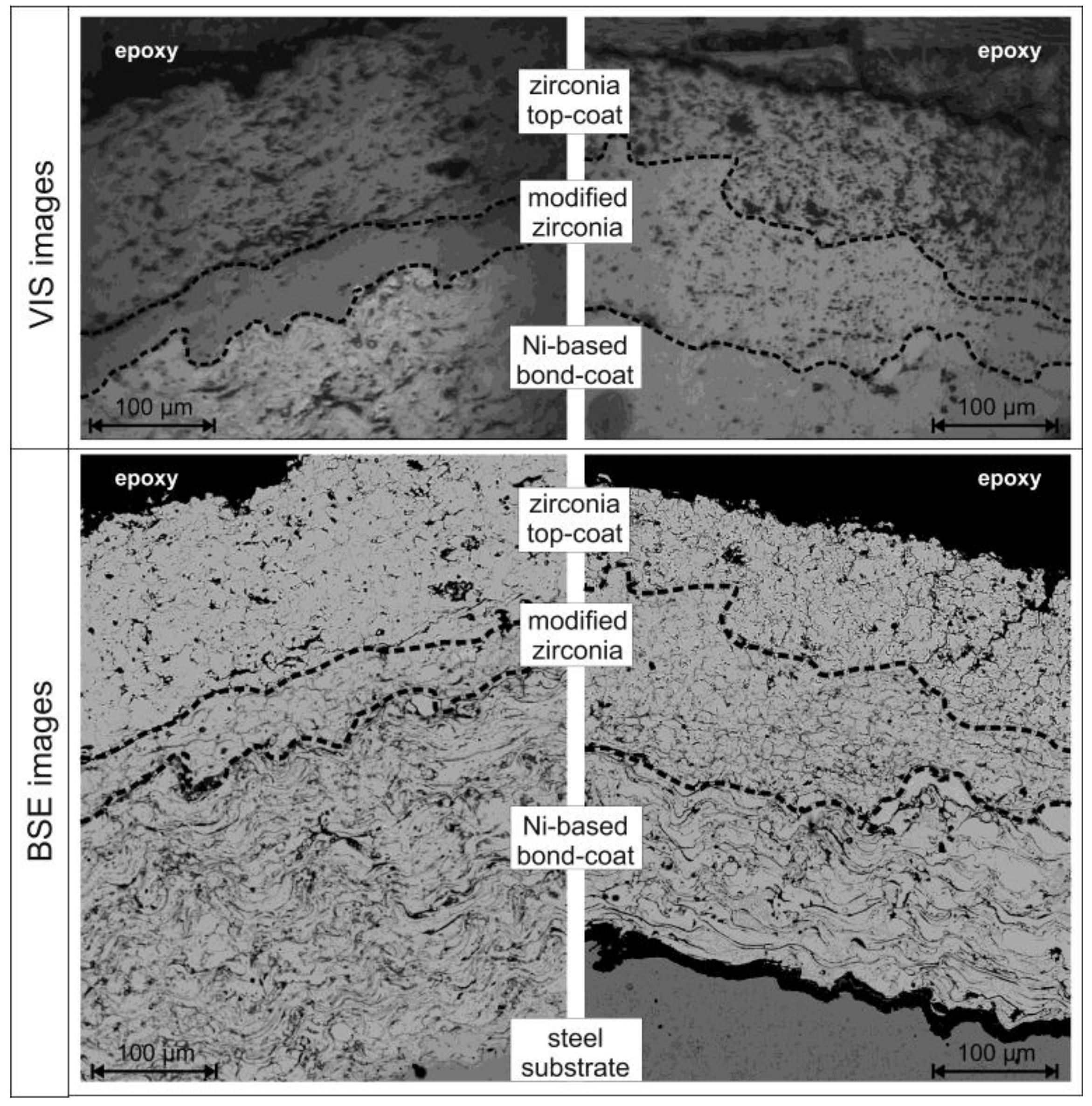
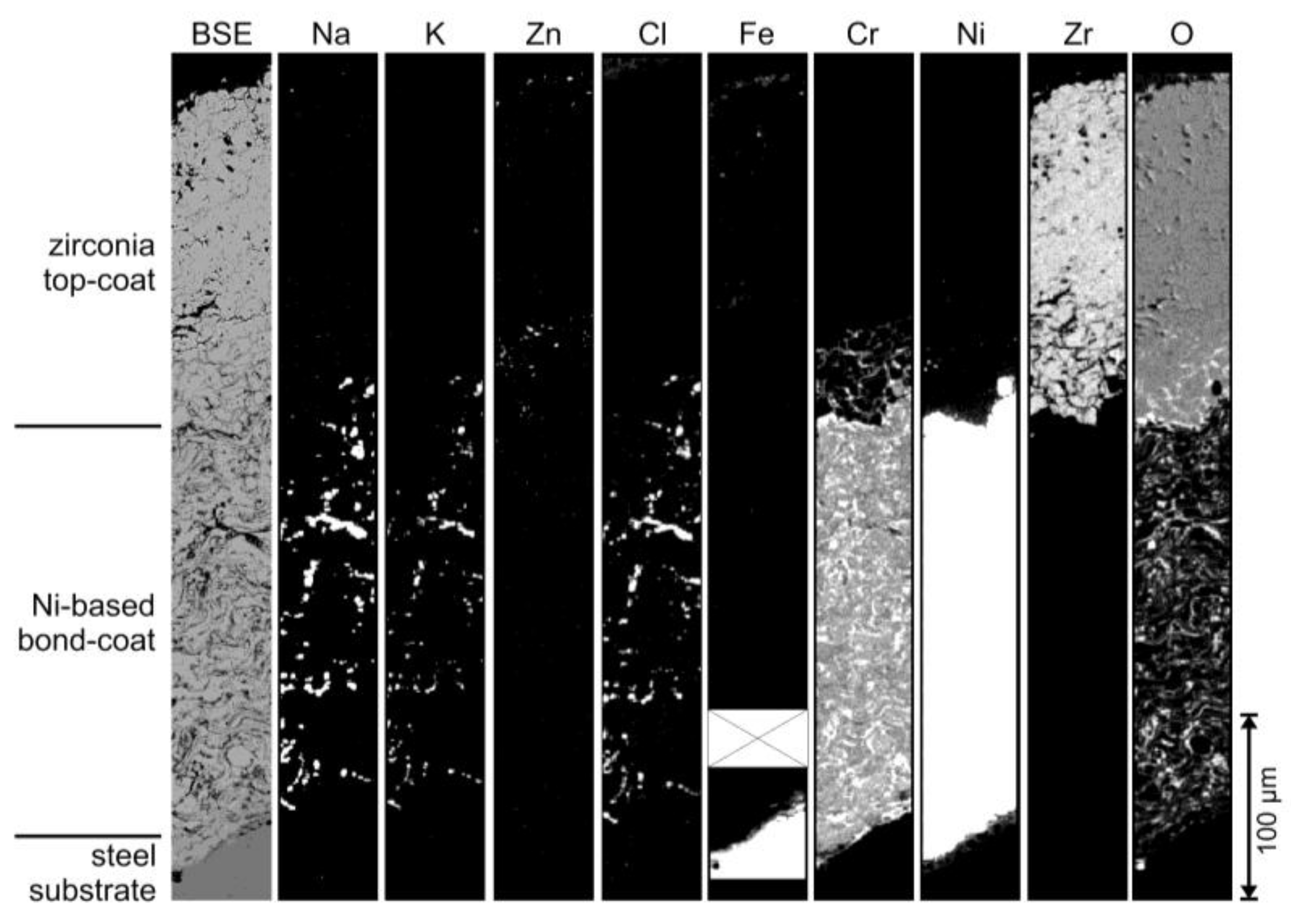
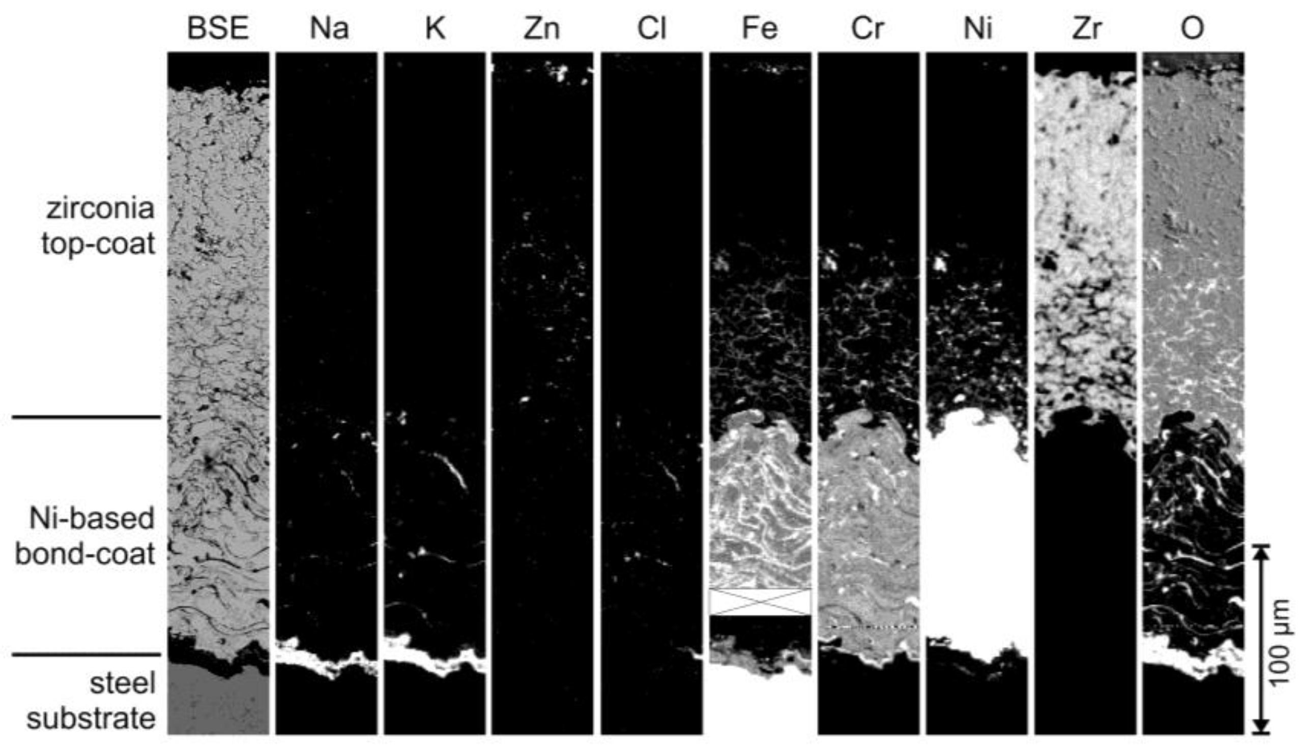
EPMA

All samples show an intact coating. Figure 3 shows the sample from position 1 (lee). In the reflected light image an approximately 50–100 µm thick area with significantly reduced porosity (7% modified zirconia, 16% unmodified zirconia) can be observed at the bottom of the zirconia top-coat, labeled as modified zirconia. The BSE image reveals that former cracks and open pores of the zirconia are filled with a secondary phase, which appears as a network of dark gray lines. By element mappings (Figure 4) and EDX analyses, this newly formed chromium-rich oxide with minor amounts of nickel and iron is assigned as metal oxide. The formation of metal oxide was accompanied by a replacement of the zirconia, as proved by a depletion of zirconium within the modified area in comparison to the unmodified area above. Additionally, small amounts of zinc can be found within the modified zirconia layer. Within the bond-coat a strong enrichment of sodium, potassium, and chlorine is observable. Their common occurrence indicates the presence of sodium and potassium chloride salts. Sulfur (sulfate) was not detected in the element mappings.

XRF

Bulk analyses of the deposits from TP 1 (uncooled test probe) show a continuously decreasing amount of SiO2, Al2O3, Fe2O3, MgO, Na2O, K2O, TiO2 from the tip of the test probe (pos. 1) to the region near the boiler wall (pos. 4), while the concentration of CaO, Cl, and partially for SO3 increase (Table 3). The high LOI indicates a high number of volatile compounds like carbonates, oxyhydroxides, chlorides, and sulfates. This dominant presence of volatile compounds near the boiler wall might be explained by the lower temperature, and hence higher condensation rate, in comparison to the central part of the flue gas flow. Notable is the presence of zirconium within the deposits at all four positions with amounts between about 300–2100 ppm. A reasonable source for the zirconium is represented by the underlying coating. The highest value of 2100 ppm at pos. 1 correlates with the observed replacement of the zirconia within the top-coat, as shown in Figure 4.

XRD

The following solid phases were determined by XRD analyses of the deposit on the surface of the luv-side of TP 1 (in decreasing amounts): anhydrite (CaSO4), melilite (gehlenite—Ca2Al[AlSiO7]), sylvite (KCl), spinel (franklinite—ZnFe2O4), magnesite (MgCO3), halite (NaCl), cristobalite (SiO2), and quartz (SiO2). These observations correspond well with XRF analysis showing high amounts of SiO2, Al2O3, CaO, Na2O, K2O, SO3, Cl, MgO, and Zn. On position 5 (lee) the observable phases differ (in decreasing amounts): calcite (CaCO3), quartz, anhydrite, halite, sylvite, cristobalite, and hematite (Fe2O3).

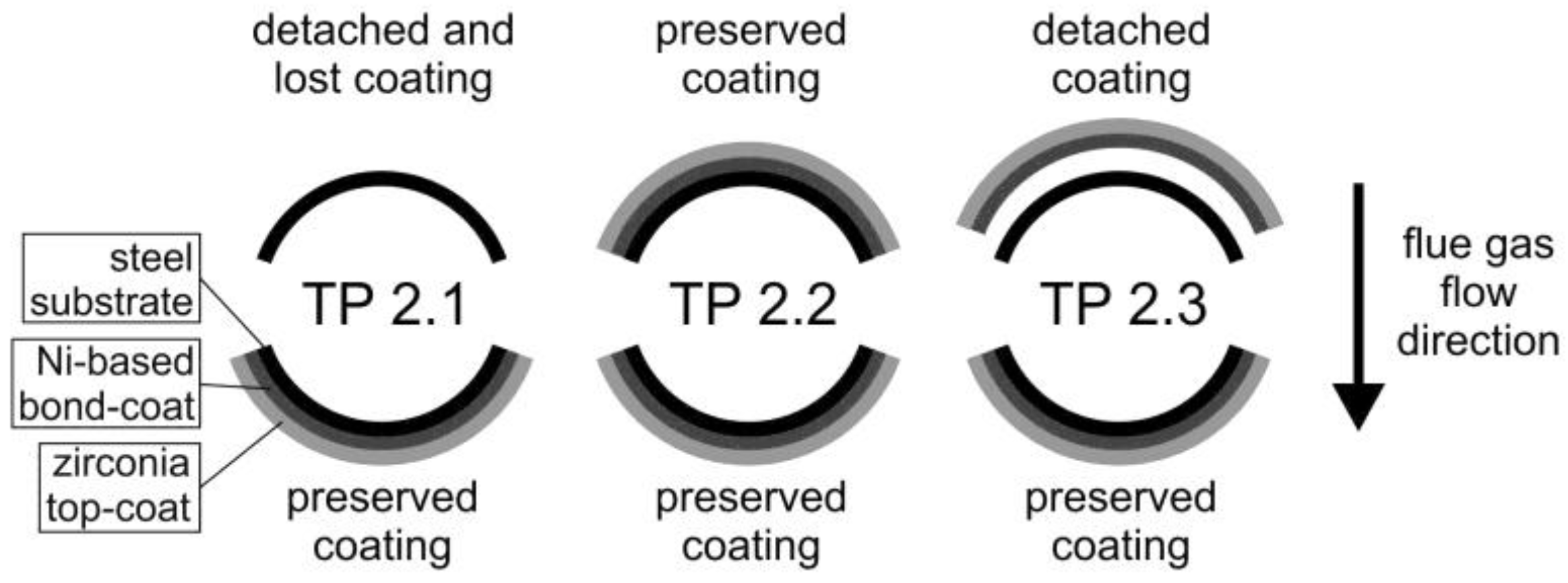
3.1.2. In Situ Test at 450 °C

The investigation of cross-sections from TP 2.1–2.3 shows various stages of corrosion attack (Figure 5). Only sample TP 2.2 does not show any detachment of the coating. In contrast, samples TP 2.1 and TP 2.3 exhibit a delamination of the multilayer coating from the steel substrate on the luv-side. On bare steel substrate surfaces a massive layer of metal oxide is observable. As indicated by EDX analyses, this layer consists of mainly iron oxide containing minor amounts of chromium, nickel, locally molybdenum, as well as sodium and potassium. The presence of sodium and potassium might represent adsorbed Na2O and K2O on the metal oxide surface. On the lee-side of sample TP 2.1 an approximately 50–250 µm thick modified area is exposed at the bottom of the zirconia top-coat, similar to that of TP 1 (Figure 3). In the reflected light mode image this area shows less porosity in comparison to the overlaying YSZ (9% modified zirconia, 19% unmodified zirconia). The BSE image shows clearly that the former open pores and cracks of the zirconia top-coat are filled by a secondary phase. Element mappings of this area (Figure 6) reveal the presence of chromium, nickel, iron, and oxygen together with minor amounts of zinc within these cracks, but no zirconium. In contrast to the uncooled test probe (TP 1), this newly formed metal oxide contains significantly more nickel and iron. Within the bond-coat an additional iron enrichment can be observed containing only traces of sodium, potassium, and chlorine. Between the steel substrate and the nickel-based bond-coat a layer of sodium, potassium, and iron oxides has formed (see Figure 6), similar to the observed oxide layer on top of an exposed steel substrate, as discussed above.

3.1.3. Summary of in Situ Tests

All test probes—at 450 °C as well as 700 °C—show a modified area at the bottom of the zirconia top-coat containing newly formed metal oxides. This modification was found on the lee-side of the test probes. Five main differences can be summarized between TP 1 and TP 2.1 (Table 4):
  • The modified area at the bottom of the zirconia top-coat is distinctly thinner for TP 1 (50–100 µm) in contrast to TP 2.1 (50–250 µm);
  • The newly formed metal oxide along the grain boundaries within the zirconia top-coat of TP 2.1 contains more nickel and iron as in TP 1;
  • TP 1 contains noticeable amounts of sodium and potassium chloride salts within the bond-coat, while TP 2.1 shows only small amounts of them;
  • TP 2.1 exhibits a significant enrichment of iron within the bond-coat;
  • TP 2.1 shows a newly formed metal oxide layer between the steel substrate and the bond-coat, which is not observable for TP 1.
The test duration of TP 2.1 (23 days) was significantly longer than that of TP 1 (14 days), and TP 2.1 exhibits a thinner multilayer coating of the zirconia top-coat and the Ni-based bond-coat in contrast to TP 1. The thicker multilayer coating of TP 1 causes a longer diffusion time for aggressive species from the flue gas to reach potential reaction partners, represented by the metal bond-coat and the steel substrate. In combination with the shorter test duration of TP 1, a retarded corrosion can be assumed. Thus, the thicker modified area within the zirconia top-coat and the newly formed layer between steel substrate and bond-coat of TP 2.1 indicates a further progress of corrosion in contrast to TP 1. Additionally, the lower surface temperature of TP 2.1 promotes the condensation of solid phases, e.g., salts. This in turn can lead to the formation of low-melting (heavy metal containing) salt melts, which can enhance the corrosion as well.
Based on these observations, the following corrosion process can be concluded: As shown by XRD analysis, the deposit contains significant amounts of sodium and potassium chloride salts (halite and sylvite) together with sulfates (anhydrite) and zinc-containing species. The combined occurrence of chloride and sulfate salts together with zinc can lead to the formation of low-melting salt melts, penetrating the coating through open pores and cracks. Due to aggressive conditions within chloride-sulfate salt melts, YSZ tends to dissolve [19]. Based on the presence of about 300–2100 ppm zirconium within the deposits on top of the coating, a partial dissolution with subsequent removal of the dissolved zirconia can be assumed. Chlorine from the combustion gases as well as from the dissociation of the salts, presumably initiates a corrosion process of the metallic bond-coat as well as the steel substrate, known as “active oxidation” [20]. This corrosion process is based on the formation of metal chlorides. Due to the high vapor pressures of such chlorides, they vaporize easily and are thus removed from their origin. When facing an increased oxygen partial pressure at or on their way to the coating surface, they are transformed to metal oxides, releasing the chlorine, which can participate again in the corrosion of the metal. The permanent presence of chlorine and oxygen within the flue gas of a WTE plant can lead to a continuing corrosion of metallic materials. The ongoing formation of metal oxides can cause a detachment of the coating from the substrate, as observable for some of the test probes described herein.

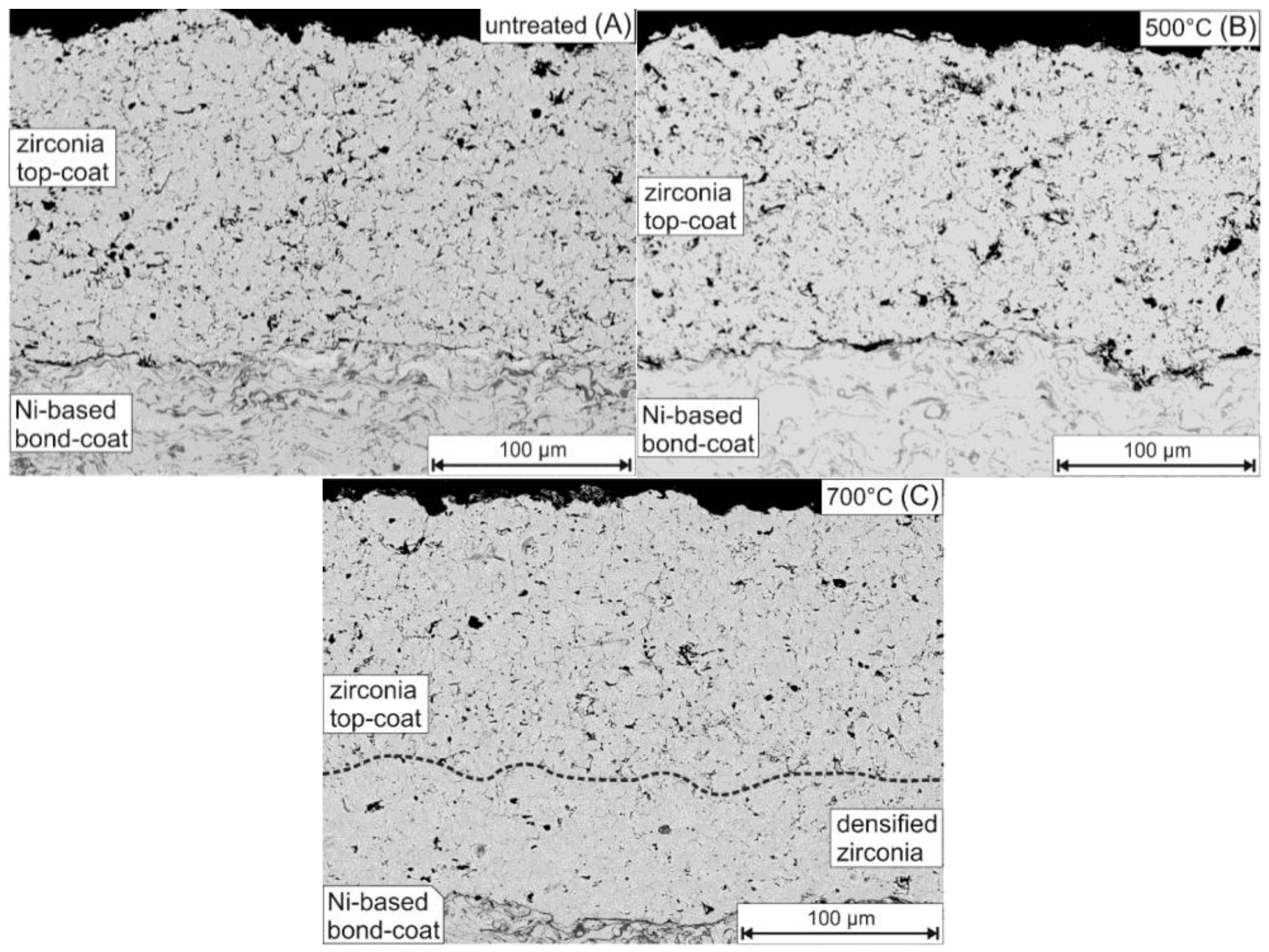
3.2. Lab-Scale Experiments

The lab-scale samples LS 1 and LS 2 were treated for two days at temperatures of 500 °C and 700 °C, respectively, under simulated WTE plant conditions (Table 1). An untreated sample (LS 3) was used as reference.
The samples with a multilayer coating show no corrosion or detachment of the coating. The YSZ top-coat of the untreated sample shows a homogeneous distribution of pores as well as microcracks (Figure 7A), representing a porosity of 12.3%. The measured porosity represents a typical value for APS-applied YSZ coatings [21]. The sample treated at 500 °C (LS 1) shows a porosity of 12.8%, similar to the untreated sample (Figure 7B). In contrast, the sample treated at 700 °C (LS 2) exhibits a profound change with the formation of two layers with different porosity (Figure 7C): the upper (outer) part, with a structure similar to the untreated sample, shows a porosity of 12.0%. The lower (inner) part, next to the nickel-based bond-coat, exhibits a considerably smaller number of cracks and pores with a porosity of 6.4%. This reduction of porosity by half is comparable to the in situ tests.
The element mappings of treated (LS 1, LS 2) and untreated (LS 3) samples show no significant difference regarding the chemical distribution within the bond- and top-coat of the multilayer. In contrast to the in situ test samples, the section of reduced porosity within the ceramic top-coat of the 700 °C treated lab-scale sample (LS 2) consists of pure YSZ (Figure 7C). These observations prove that the densification of the YSZ without any addition of zirconium is possible, which represents an extension to prior studies, where additional zirconium was seen as a prerequisite for a successful densification [14,15,17]. This leads to the question concerning the densification mechanism. Two different theories are currently in discussion: One option follows the theory of a solvothermal process proposed by Fehr and coworkers [14], Masset and coworkers [15] and Ye [17], suggesting a mobilization of the zirconium through a vapor phase by the formation of zirconium chloride (ZrClx). The authors describe a recrystallization of ZrO2 as a consequence of an increased oxygen partial pressure in open pores, which is expected to cause the observed densification. Since no zirconium was added for the experiments described herein, it implies a partial solution of the zirconia within the top-coat to provide the zirconium for the recrystallization process. Another option is a densification mechanism by grain growth via sintering in combination with a partial phase transformation from tetragonal to monoclinic zirconia (going along with a volume increase of ~4%): In general, a significant grain growth via sintering of YSZ ceramics as well as a phase transformation from tetragonal to monoclinic, initiated by a temperature driven diffusion of yttrium, occurs at temperatures above 1100 °C [22,23,24]. Besides the significantly lower temperatures of the experiments described herein, both processes would affect the whole top-coat instead of creating a partially densified ceramic, as shown in Figure 7C. Notable is the observation of Pasquevich and coworkers [25], who found an accelerated grain growth of YSZ under a chlorine-bearing atmosphere at even lower temperatures of 940 °C, additionally accompanied by a partial phase transformation from tetragonal to monoclinic zirconia. Thus it seems a possible explanation is that a locally chlorine-enriched atmosphere at the bottom of the top-coat promotes the partial densification at 700 °C via grain growth, based on a combination of sintering and phase transformation. Since grain growth via sintering positively correlates with the temperature, our assumption supports the observations from prior studies [14,15,17], which found a higher densification rate at higher temperatures.
The vapor phase transport via zirconium chloride species and the chlorine-induced sintering accompanied by a phase transformation, are based on the interaction with chlorine, which was present during the whole experiment. Therefore, the densification of the zirconia can be interpreted as a combined mechanism of both.

4. Conclusions

In situ experiments inside a WTE plant with test probes coated with a multilayer coating of a nickel-based bond-coat and a YSZ top-coat show distinct corrosion phenomena. A detachment of the coating was observed for cooled test probes, which represent the actual conditions of use as, for example, superheater tube. A partial dissolution of the zirconia top-coat enables an enhanced penetration of the coating by aggressive gases, leading to the formation of newly formed metal oxides within the YSZ top-coat and between bond-coat and steel substrate.
Lab-scale experiments were done under an extremely aggressive gas atmosphere to test the corrosion resistance of samples with a multilayer coating of a nickel-based bond-coat and an YSZ top-coat. Samples with a multilayer coating show no detachment of the coating. For the experiment at 700 °C a partial densification of the zirconia top-coat was achieved. The results clearly show that this densification process can happen without any additional zirconium in the gas flow. This means that the range of the conditions leading to a densification proposed by Fehr and coworkers [14], Masset and coworkers [15] and Ye [17] can be enlarged. Presumably the densification process is based on a gas phase transport of the zirconium in combination with grain growth via sintering, accompanied by a partial phase transformation from tetragonal to monoclinic zirconia. The latter one is accompanied by a volume increase of approximately 4%, representing a sufficient amount to close microcracks of the YSZ top-coat.
Studies from Wöllmer and coworkers [26] have shown an improved corrosion resistance of solvothermally pretreated test probes. This pretreatment might follow a routine, described herein for the lab-scale experiments. The existence of a densified zirconia layer can reduce the diffusion of aggressive gases, hence reducing the corrosion of the steel substrate. Thus a pretreatment of the ceramic top-coat seems to be a necessary step in order to enable the multilayer coating to act as a long-term corrosion-resistant coating for application in WTE plants. Due to the small thickness of the APS-applied multilayer coating, this coating layout can be a cost efficient alternative for currently used 2–3 mm thick nickel-based weld overlays. In particular, membrane walls and superheater tubes come into focus of interest, since they are the object of severe corrosion attack within a WTE plant.

Acknowledgments

The authors thank Hilger Lohringer for EPMA sample preparation and Klaus Dotzler for the preparation of the thermally sprayed coatings. This work was funded by the Federal Ministry of Education and Research (BMBF) within the MatRessource research program TS-Protect (03X3569). The research project TS-Protect has been partially initiated by Karl Thomas Fehr from the Ludwig-Maximilians-Universität München. He suddenly passed away in the earlier stage of this project. The authors are grateful to him for precious advices and scientific understanding of the solvothermal process and chemistry.

Author Contributions

Dirk Müller performed the lab-scale experiments; Silke Wöllmer and Konrad Rieger performed the in-situ tests; Dirk Müller performed the EPMA and XRD analyses; Donjá Aßbichler performed the XRF analyses; Dirk Müller, Silke Wöllmer, Donjá Aßbichler, Martin J. Murer, Soraya Heuss-Aßbichler and Patrick J. Masset interpreted and discussed the results; Horst Hill and Carsten Härtel contributed materials; Dirk Müller, Silke Wöllmer and Soraya Heuss-Aßbichler wrote the paper.

Conflicts of Interest

The authors declare no conflict of interest.

References

  1. Warnecke, R. Fünfzig Jahre und kein bisschen weise—Korrosion und Verfahrenstechnik in thermischen Abfallbehandlungsanlagen. In Energie aus Abfall; Thomé-Kozmiensky, K.J., Beckmann, M., Eds.; TK Verlag: Neuruppin, Germany, 2014; Volume 11, pp. 441–457. (In German) [Google Scholar]
  2. Noguchi, M.; Yakuwa, H.; Miyasaka, M.; Yokono, M.; Matsumoto, A.; Miyoshi, K.; Kosaka, K.; Fukuda, Y. Experience of superheater tubes in municipal waste incineration plant. Mater. Corros. 2000, 51, 774–785. [Google Scholar] [CrossRef]
  3. Frandsen, F.J. Utilizing biomass and waste for power production—A decade of contributing to the understanding, interpretation and analysis of deposits and corrosion products. Fuel 2005, 84, 1277–1294. [Google Scholar] [CrossRef]
  4. Antunes, R.A.; de Oliveira, C.L. Corrosion in biomass combustion: A materials selection analysis and its interaction with corrosion mechanisms and mitigation strategies. Corros. Sci. 2013, 76, 6–26. [Google Scholar] [CrossRef]
  5. Spiegel, W.; Herzog, T.; Magel, G.; Müller, W.; Schmidl, W.; Albert, F.-W. Korrosion in Abfallverbrennungsanlagen. In Dampferzeugerkorrosion; Born, M., Ed.; SAXONIA Standortentwicklungs- und -verwaltungsgesellschaft mbH: Freiberg, Germany, 2013; pp. 9–95. (In German) [Google Scholar]
  6. Spiegel, M. Influence of gas phase composition on the Hot Corrosion of steels and nickel-based alloys beneath a (Ca-Na-K)-sulfate mixture containing PbSO4 and ZnSO4. Mater. Corros. 2000, 51, 303–312. [Google Scholar] [CrossRef]
  7. Phongphiphat, A.; Ryu, C.; Bin Yang, Y.; Finney, K.N.; Leyland, A.; Sharifi, V.N.; Swithenbank, J. Investigation into high-temperature corrosion in a large-scale municipal waste-to-energy plant. Corros. Sci. 2010, 52, 3861–3874. [Google Scholar] [CrossRef]
  8. Montgomery, M.; Hansson, A.N.; Jensen, S.A.; Vilhelmsen, T.; Nielsen, N.H. In situ corrosion testing of various nickel alloys at Mabjerg waste incineration plant. Mater. Corros. 2013, 64, 14–25. [Google Scholar] [CrossRef]
  9. Oksa, M.; Auerkari, P.; Salonen, J.; Varis, T. Nickel-based HVOF-coatings promoting high temperature corrosion resistance of biomass-fired power plant boilers. Fuel Process. Technol. 2014, 125, 236–245. [Google Scholar] [CrossRef]
  10. Schülein, R.W.; Born, M.; Korb, J. Thermische Spritzschichten zur Minderung von Schadensfällen durch Korrosion und Erosion. VGB PowerTech J. 2006, 7, 58–64. [Google Scholar]
  11. Schmidl, W. Erfahrungen mit thermisch gespritzten Schichten als Korrosionsschutz auf Wärmetauscherflächen in reststoffbefeuerten Dampferzeugern. In Energie aus Abfall; Thomé-Kozmiensky, K.J., Beckmann, M., Eds.; TK Verlag: Neuruppin, Germany, 2014; Volume 11, pp. 593–610. (In German) [Google Scholar]
  12. Hussain, T.; Simms, N.J.; Nicholls, J.R. Modelling fireside corrosion of thermal sprayed coatings in co-firing of coal/biomass. Mater. Corros. 2013, 65, 197–205. [Google Scholar] [CrossRef]
  13. Bendix, D.; Tegeder, G.; Crimmann, P.; Metschke, J.; Faulstich, M. Development of thermal sprayed layers for high temperature areas in waste incineration plants. Mater. Corros. 2008, 59, 389–392. [Google Scholar] [CrossRef]
  14. Fehr, K.T.; Ye, Y.; Faulstich, M.; Weih, C.; Wolf, G. Ein neues Verfahren zur Optimierung oxidkeamischer Schutzschichten. In Moderne Beschichtungen zum Verschleißschutz von Werkzeugen; Faulstich, M., Geiger, M., Kukla, H., Wolf, G., Eds.; DORNER PrintConcept GmbH & Co. KG: Sulzbach-Rosenberg, Germany, 2012; Volume 7, pp. 51–78. (In German) [Google Scholar]
  15. Masset, P.J.; Faulstich, M.; Fehr, K.T.; Weih, C.; Wolf, G.; Ye, Y. Chemical densification of oxide based coatings for high temperature wear and corrosion resistance. ECS Trans. 2013, 50, 109–116. [Google Scholar] [CrossRef]
  16. Fehr, K.T.; Ye, Y.; Wolf, G. Verfahren zur Herstellung einer keramischen Schicht auf einer aus einer Ni-Basislegierung gebildeten Oberfläche. Patent DE 10.2012.200.560, 16 January 2012. (In German)[Google Scholar]
  17. Ye, Y. Modification of Thermally Sprayed Ceramic Oxide Coatings by Chemical Densification Processing. Ph.D. Thesis, Ludwig-Maximilians-Universität München, Munich, Germany, 2016. [Google Scholar]
  18. Karger, M.; Vaßen, R.; Stöver, D. Atmospheric plasma sprayed thermal barrier coatings with high segmentation crack densities: Spraying process, microstructure and thermal cycling behavior. Surf. Coat. Technol. 2011, 206, 16–23. [Google Scholar] [CrossRef]
  19. Müller, D.; Heuss-Aßbichler, S. Behavior of yttria-stabilized zirconia in the presence of molten salts: Part 1—Dissolution and recrystallization phenomena. J. Eur. Ceram. Soc. 2016, 36, 3495–3503. [Google Scholar] [CrossRef]
  20. Grabke, H.J.; Reese, E.; Spiegel, M. The effects of chlorides, hydrogen chloride, and sulfur dioxide in the oxidation of steels below deposits. Corros. Sci. 1995, 37, 1023–1043. [Google Scholar] [CrossRef]
  21. Deshpande, S.; Kulkarni, A.; Sampath, S.; Herman, H. Application of image analysis for characterization of porosity in thermal spray coatings and correlation with small angle neutron scattering. Surf. Coat. Technol. 2004, 187, 6–16. [Google Scholar] [CrossRef]
  22. Siebert, B.; Funke, C.; Vaßen, R.; Stöver, D. Changes in porosity and Young’s Modulus due to sintering of plasma sprayed thermal barrier coatings. J. Mater. Process. Technol. 1999, 92–93, 217–223. [Google Scholar] [CrossRef]
  23. Wang, N.; Zhou, C.; Gong, S.; Xu, H. Heat treatment of nanostructured thermal barrier coating. Ceram. Int. 2007, 33, 1075–1081. [Google Scholar] [CrossRef]
  24. Krogstad, J.A.; Krämer, S.; Lipkin, D.M.; Johnson, C.A.; Mitchell, D.R.G.; Cairney, J.M.; Levi, C.G. Phase stability of t’-zirconia-based thermal barrier coatings: Mechanistic insights. J. Am. Ceram. Soc. 2011, 94, S168–S177. [Google Scholar] [CrossRef]
  25. Pasquevich, D.M.; Lovey, F.; Caneiro, A. Structural and Microstructural Changes in Zirconia in Dilute Chlorine Atmosphere. J. Am. Ceram. Soc. 1989, 72, 1664–1667. [Google Scholar] [CrossRef]
  26. Wöllmer, S.; Förg, A.; Schuster, S.; Masset, P.J. Solvothermal modified layers against high temperature corrosion. Mater. Sci. Forum 2015, 825–826, 621–627. [Google Scholar] [CrossRef]
Figure 1. (A) Layout of an uncoated test probe for in situ experiments; (B) Test probe TP 1 after 14 days in a waste-to-energy (WTE) plant. Positions 1–4: flue gas-facing side (luv), position 5: flue gas-away side (lee).
Coatings 06 00036 g001
Figure 2. Schematic diagram of the experimental setup for lab-scale experiments.
Coatings 06 00036 g002
Figure 3. Reflected light (VIS) and back-scattered electron (BSE) images of an uncooled test probe TP 1 (700 °C) (left) and a cooled test probe TP 2.1 (450 °C) (right).
Coatings 06 00036 g003
Figure 4. Back-scattered electron (BSE) image in combination with element mappings of sodium, potassium, zinc, chlorine, iron, chromium, nickel, zirconium, and oxygen of the multilayer coating from the lee-side of the uncooled test probe (TP 1—700 °C for 14 days). The element mapping of Fe is separated into two parts with different scales in order to visualize the distribution of different amounts within the coating: upper part—low amount (25–250 cts); lower part—high amount (400–1200 cts) of Fe.
Coatings 06 00036 g004
Figure 5. Condition of the coatings of the cooled test probes (TP 2.1, TP 2.2, TP 2.3) after 23 days within a WTE plant. Samples were prepared from the luv- and lee-side.
Coatings 06 00036 g005
Figure 6. Back-scattered electron (BSE) image in combination with element mappings of sodium, potassium, zinc, chlorine, iron, chromium, nickel, zirconium, and oxygen of the multilayer coating from the lee-side of a cooled test probe (TP 2.1—450 °C for 23 days). The element mapping of Fe is separated into two parts with different scales in order to visualize distribution of different amounts within the coating: upper part—low amount (25–250 cts); lower part—high amount (400–1200 cts) of Fe.
Coatings 06 00036 g006
Figure 7. Back-scattered electron images of lab-scale experiment samples: (A) as-sprayed, untreated sample (LS 3); (B) sample treated for 2 days at 500 °C (LS 1); and (C) sample treated for 2 days at 700 °C (LS 2), showing a modified, less porous area of the zirconia top-coat, next to the nickel-based bond-coat.
Coatings 06 00036 g007
Table 1. Overview of the experiments (TP: test probes for in situ investigations; LS: lab-scale samples).
SampleCoatingTreatment
AtmosphereTemperature (°C)Additional Salt Mixture
N2/HCl/O2 (vol.%)
TP 1Inconel 625 + YSZWTE plant~700
TP 2.1Inconel 625 + YSZWTE plant~450
TP 2.2Inconel 625 + YSZWTE plant~450
TP 2.3Inconel 625 + YSZWTE plant~450
LS 1Inconel 625 + YSZ97/2.1/0.9500KCl, ZnCl2, K2SO4, ZnSO4
LS 2Inconel 625 + YSZ97/2.1/0.9700KCl, ZnCl2, K2SO4, ZnSO4
LS 3Inconel 625 + YSZuntreated reference
Table 2. Composition of the bond-coat material Nibasit 625-P. Data from DEW, Krefeld, Germany.
ElementsContent (wt.%)
Cr22.00
Mo9.00
Fe4.00
Nb3.60
C<0.06
Nibalance
Table 3. Results of X-ray fluorescent (XRF) analyses from surface deposits of an uncooled test probe (TP 1), placed for 14 days at 700 °C in a WTE plant. Sample positions 1–4 are shown in Figure 1B.
ElementsSample Position
1234
SiO2 (wt.%)15.5814.5013.4211.37
Al2O38.077.987.236.36
Fe2O3 T3.122.822.772.15
MnO0.380.430.400.32
MgO3.323.152.922.59
CaO19.7228.3628.6828.11
Na2O9.976.285.715.33
K2O5.974.123.843.82
TiO21.991.871.751.70
P2O52.101.921.68
SO317.8618.8320.8416.89
Cl0.941.311.193.04
Ba0.230.190.210.23
Cr0.120.170.130.06
Cu0.050.020.020.03
Ni0.030.020.020.02
Pb0.010.010.01
Rb0.010.010.010.01
Sb0.100.070.330.14
Sn0.060.030.190.04
Sr0.030.040.040.04
Zn3.471.942.071.04
Zr0.210.030.140.13
LOI6.777.786.1014.88
Total100.1199.9699.9399.99
Table 4. Summarized observations for the in situ test probes.
SampleTP 1TP 2.1
experiment duration14 days23 days
temperature700 °C450 °C
zirconia top-coatthickness of the modified zirconia layer50–100 µm50–250 µm
composition of the metal oxide within the modified zirconia layerCr, (±Ni), (±Fe)Cr, Ni, (±Fe)
Ni-based bond-coatsalt amount within the bond-coatsignificant amounts of NaCl and KClsmall amounts of NaCl and KCl
iron amount within the bond-coatnon-existentmoderate amount
newly formed iron-oxide layer between bond-coat and steel substratenon-existentexistent, +Na, +K

