
Modeling of MMC for Fast and Accurate Simulation of Electromagnetic Transients: A Review


Department of Electric Power Engineering, Norwegian University of Science and Technology (NTNU), O.S. Bragstads Plass 2E, 7491 Trondheim, Norway
*
Author to whom correspondence should be addressed.
Energies 2017, 10(8), 1161; https://0-doi-org.brum.beds.ac.uk/10.3390/en10081161
Submission received: 22 April 2017
/
Revised: 29 June 2017
/
Accepted: 1 August 2017
/
Published: 7 August 2017
Abstract
:Over the past decade, modular multilevel converters have evolved as the preferred choice for high voltage conversion systems. The design of the converter poses a computational challenge to the classical electromagnetic transient simulation techniques, for which the existing literature proposes numerous simplified and computationally-efficient equivalent representations. Despite the extensive collection of proposed models, the literature lacks a systematic comparison of these representations, which could enable their appropriate selection based on the specific simulation objectives. In light of these requirements, this article presents a comprehensive review of MMC models and discusses their applicability for parallel and real-time simulation. Using PSCAD/EMTDC simulations, the models are objectively compared with regards to computational efficiency and accuracy for various transient conditions. In addition, the paper also presents a brief account of MMC operation and the associated control and modulation system.
1. Introduction
Modular multilevel converters, a recent invention by Lesnicar and Marquardt [1,2,3,4], are gradually becoming the technology of choice in high-voltage direct current (HVDC) power transmission for grid integration of large-scale offshore wind farms, bulk power transmission systems and multi-terminal HVDC grids [5,6,7,8,9,10,11,12]. With its multilevel and modular realization, this converter topology is scalable to very high power or voltage levels; with reduced switching frequency, it has very low switching losses; and with its nearly sinusoidal waveform, it has minimal filter requirement [13,14,15].
Each phase of an MMC-HVDC terminal can consist of several hundreds of identical submodules that switch a module capacitor in and out of the circuit to synthesize stepped AC or constant DC terminal voltages. This operation requires sophisticated control and modulation techniques. Furthermore, accurate modeling and computer simulation of the MMC converter together with the associated power system are essential for its efficient design, validation of the control system and operational planning. Electromagnetic transient solvers are generally utilized for the simulation of such power electronic and electric power integrative systems. However, the design of MMC poses a computational challenge to the classical electromagnetic transient simulations techniques. Independent operation of submodules necessitates their explicit modeling, which leads to hundreds of nodes and semiconductor devices in the equivalent models. This time-varying topology with hundreds of nodes leads to the excessive computational load on solvers based on the classical nodal admittance method. Existing literature presents a number of efficient equivalent models to address the high computational load of MMC simulations [16,17,18,19,20,21,22,23]. Using the most recent literature, this paper aims to provide a review of the models that are most suitable for EMT studies. This further enables their hierarchization for different levels of power converter and system studies.
The paper starts with a brief description of topology, operating principles, control and modulation methods for MMC in Section 2. Section 3 presents a literature review of equivalent models, suitable for EMT studies. Simulation results in Section 4 examine the efficacy of the models under transient conditions. Finally, conclusions are drawn in Section 5.
2. Converter System
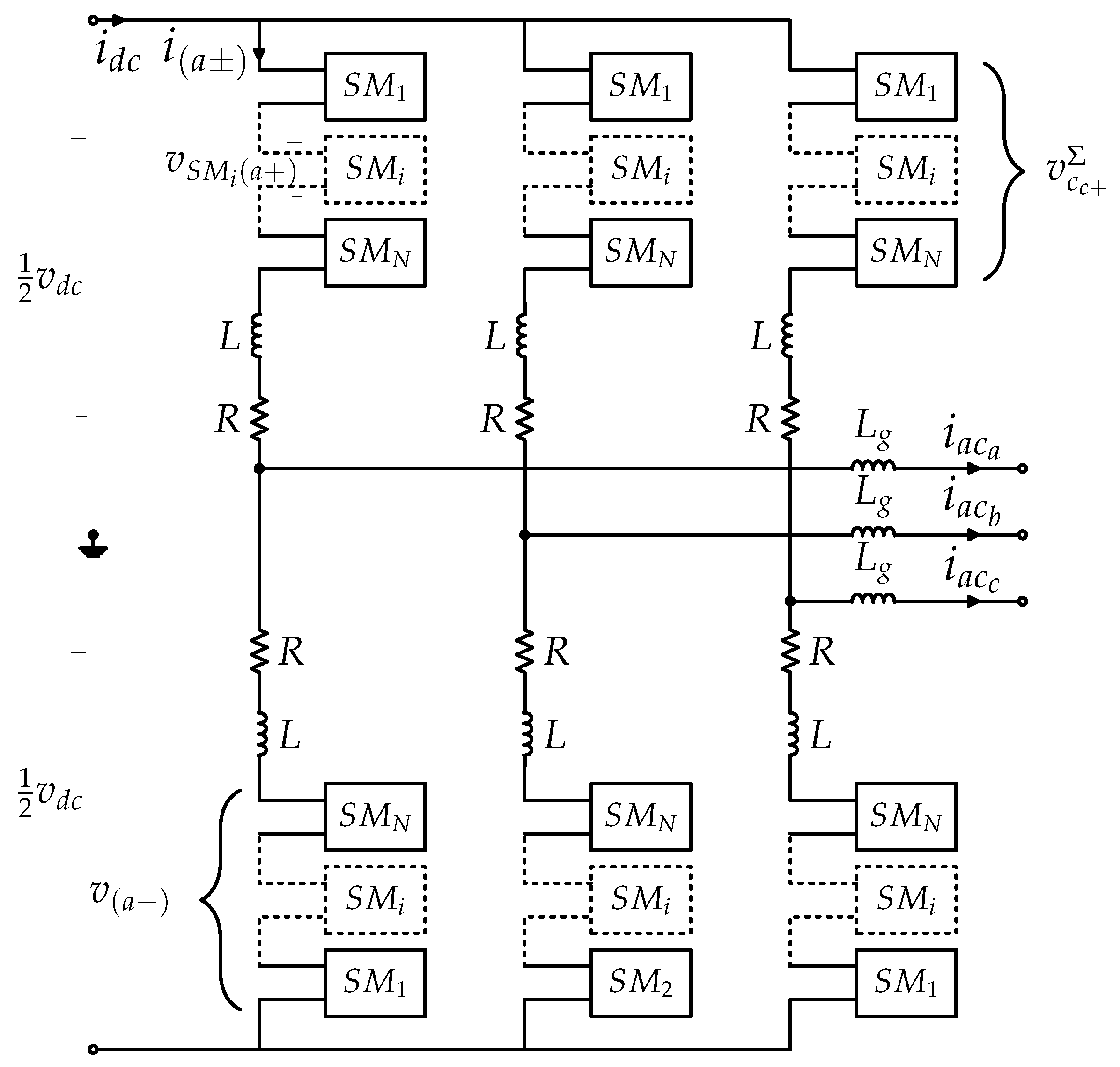
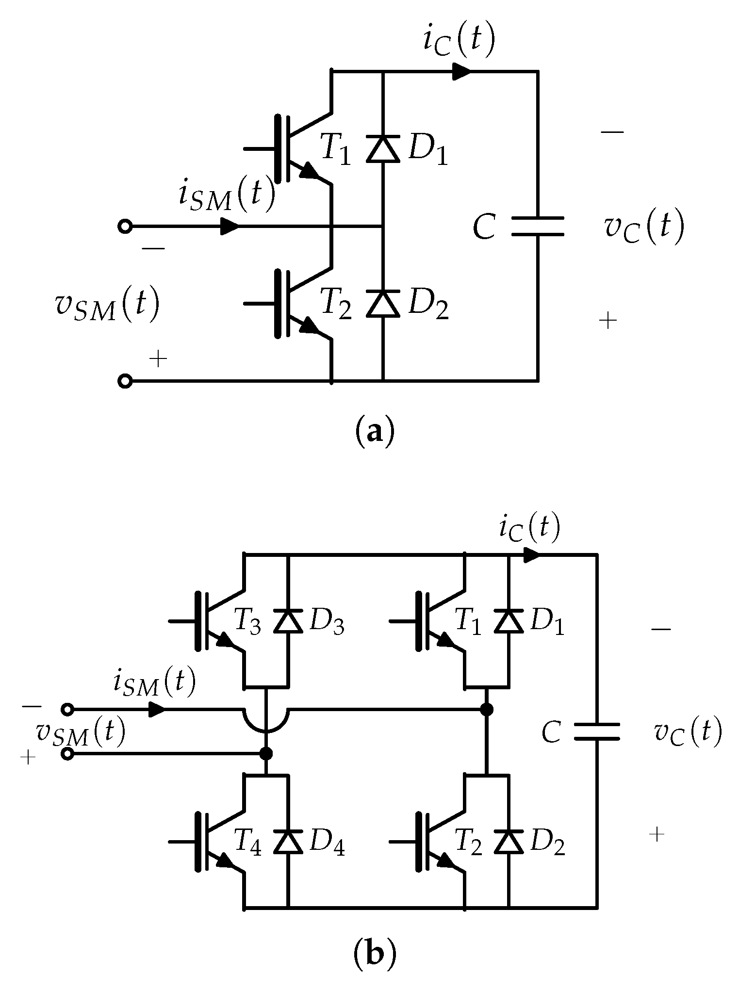
The double-star-configured MMC [24,25,26], referred to as the MMC here, is illustrated in Figure 1. Each phase leg comprises two arms that connect DC and AC terminals through N cascaded/series submodules (SMs) and an arm reactor. Submodules are two terminal devices, composed of an IGBT-based converter and a capacitor. These modules can be half-bridge, full-bridge or other hybrid configuration cells [27]. Full-bridge submodule MMCs, with their DC fault handling capacity, find specialized application in overhead HVDC transmission systems [28]; while half-bridge submodules (HBSM), with fewer semiconductor devices and subsequently lower losses [29], are the dominant type of submodule for the more widely-used underground and submarine HVDC transmission systems and, therefore, the prime focus of this study.
HBSMs are composed of two IGBTs with freewheeling diodes and a capacitor as illustrated in Figure 2a. With the complementary operation of IGBTs, an HBSM can insert positive (inserted state) or zero (bypassed state) voltage based on the gate signals (), irrespective of the direction of the current. Therefore, with this topology, each arm in MMC behaves as a controllable, unipolar voltage source [30]. In addition, turning off of both switches results in the blocked state where only freewheeling diodes allow the flow of current, and their conduction is dependent on their voltage and currents. With half-bridge SMs, the converter cannot suppress DC side faults. The blocked state restricts current flow only in one of the two potential directions; therefore, DC breakers or breakers on the AC feed are necessary for such a converter system [30]. Table 1 summarizes the operating modes of the half-bridge submodule.
2.1. Dynamics
Terminal and internal dynamics of an individual submodule are dictated by the instantaneous and historic values of the arm current/voltage, capacitor voltage and the state of the IGBTs. Nevertheless, for simplicity, the dynamics of all submodules in an arm can be taken as equivalent. As a result, the average dynamics of an arm can be modeled by Equations (1)–(3) (refer to the Nomenclature for symbols’ interpretation).
where the insertion index, (), gives the average number of submodules inserted in an arm and represent the average unified internal voltage and current dynamics of all submodules.
From Kirchhoff’s voltage law, the AC side operation of MMC is defined by [31]:
while inserted leg voltage, , and circulating current , dictate the DC side operation of a leg, i.e.,
This reveals that with independent control of submodules, each arm of an MMC behaves as a variable voltage source, which allows for independent control on all AC voltages and the DC voltage. The AC side operation of MMC as seen from Equations (4)–(5) is defined by internal electromotive force (emf), , and internal impedance, . Through appropriate selection of insertion indices and the resulting difference of arm voltages, MMC can attain the desired voltage on the AC side together with the desired real and reactive power exchange with the grid, if any. Similarly, the DC voltage as revealed by Equations (6)–(7) is controllable by insertion indices and the resulting sum of arm voltages. The presence of circulating current in phase legs is also revealed by Equations (6)–(7). Circulating current in a phase leg is composed of a DC component, which is essential for the transmission of real power. Moreover, voltage imbalance in phase legs results in additional harmonic components in the phase leg. Further analysis of the converter internal dynamics as presented in [32,33,34] reveals the presence of even order harmonics in circulating current, of which the second order is dominant.
2.2. Control System
The control system for an MMC is hierarchized as:
- Upper-level
- Current control
- Voltage balancing control
The objective of current controllers is to determine the reference voltage waveforms to attain desired voltage and power flow characteristics. This control can be realized by direct or vector methods [35,36] for the grid-connected converter or through droop control [37] in islanded or weak-grid systems.
The circulating current harmonics tend to increase the losses in the system and increase the rating requirements for system components. Thus, mitigation of these harmonics is needed. These harmonics can be regulated by active compensation of voltage imbalance in a phase leg through control methods [38,39,40,41,42,43,44] or can be attenuated by tuned arm filters [45,46].
Voltage balancing control ensures that capacitor voltage is more or less constant across all submodules. This requires instantaneous control to ensure charging of depleting capacitors and discharging of charged capacitors. Superposition of DC and fundamental current in an arm implies that the current through each arm changes its polarity. Therefore, within a one-time cycle, there are instants of charging and discharging currents. Such voltage balancing techniques include circular transposition of carrier waves [47,48] or calculated approaches such as the capacitor voltage rank-based method [3,49] and a combination of averaging and balancing controls [24,50,51,52,53].
2.3. Modulation Strategy
The modulation system for MMCs enables energy balance in the arms of the converter and voltage balancing across individual submodule capacitors and can be classified as follows.
2.3.1. Arm Level Modulation
The objective of this modulation is to generate insertion indices for all arms of MMC, to achieve desired reference values of AC/DC power and or voltage as dictated by the control system. These insertion indices, in turn, determine the number of submodules inserted in an arm at a given instant. In addition, this modulation ensures that the inserted voltage in a phase leg () and the arm cumulative capacitor voltage () correspond to the DC link voltage.
The modulation can be implemented through the direct calculation of insertion indices or through feedback control as summarized in Table 2.
2.3.2. Module Level Modulation
The objective of the module level modulation (MLM) methods is to translate reference values of insertion indices from the arm-level modulation to the gate signals for each submodule. These switching signals for individual submodules not only influence the voltage waveform on the AC and DC sides of the converter as a whole, but also control the charging and discharging of submodule capacitors; therefore, this level of modulation needs to conform with the arm-level modulation and the voltage balancing control. Such methods are summarized in Table 3.
3. Modeling
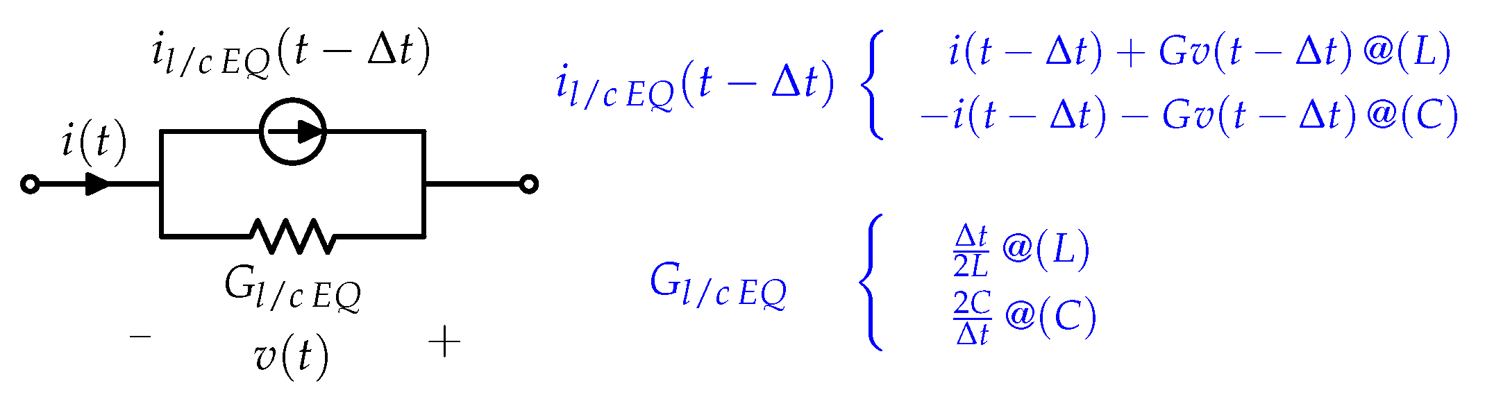
In power electronic systems, switching operation is crucial and the prime source of transients in the system. Therefore, for MMCs, EMT-type solvers are utilized for simulations. These solvers employ the trapezoidal rule of integration to approximate lumped elements as illustrated in Figure 3 [81]; while distributed components are modeled using Bergeron’s method [82]. With this representation, the system is resolved in the time domain using the nodal admittance method [83]. Non-linear characteristics of semiconductor devices and the subsequent time-dependent topology of systems require repetitive re-triangulation and interpolations for exact tracking of switching instances [84,85,86] and tend to make the simulation of power electronics systems computationally intensive [87,88].
Unlike conventional current and voltage source converters, where the series array of semiconductors can be modeled as a single device, MMCs employ submodules with an independent operation. Therefore, MMC simulation expects explicit representation for each semiconductor device for most converter studies.
3.1. MMC Classical Modeling
Classical simulation techniques utilize the nodal admittance method on the EMT equivalent representations. Semiconductor devices can be modeled using [23]:
- Full physics: differential equations or equivalent circuits.
- Nonlinear IGBTs: ideal switches with nonlinear diodes.
- Bi-value resistor: on () and off () resistor.
These models preserve the circuit configuration of the MMC and simultaneously solve the entire system using the nodal admittance method. Even with a bi-value resistor representation for semiconductor devices, an arm is mathematically represented by a matrix of dimension in this model. With frequent switching, this solution method requires repetitive re-triangulation and interpolations of the system matrix. Therefore, this modeling method tends to be computationally intensive and does not inherently allow parallel computation, making it unsuitable for real-time simulations.
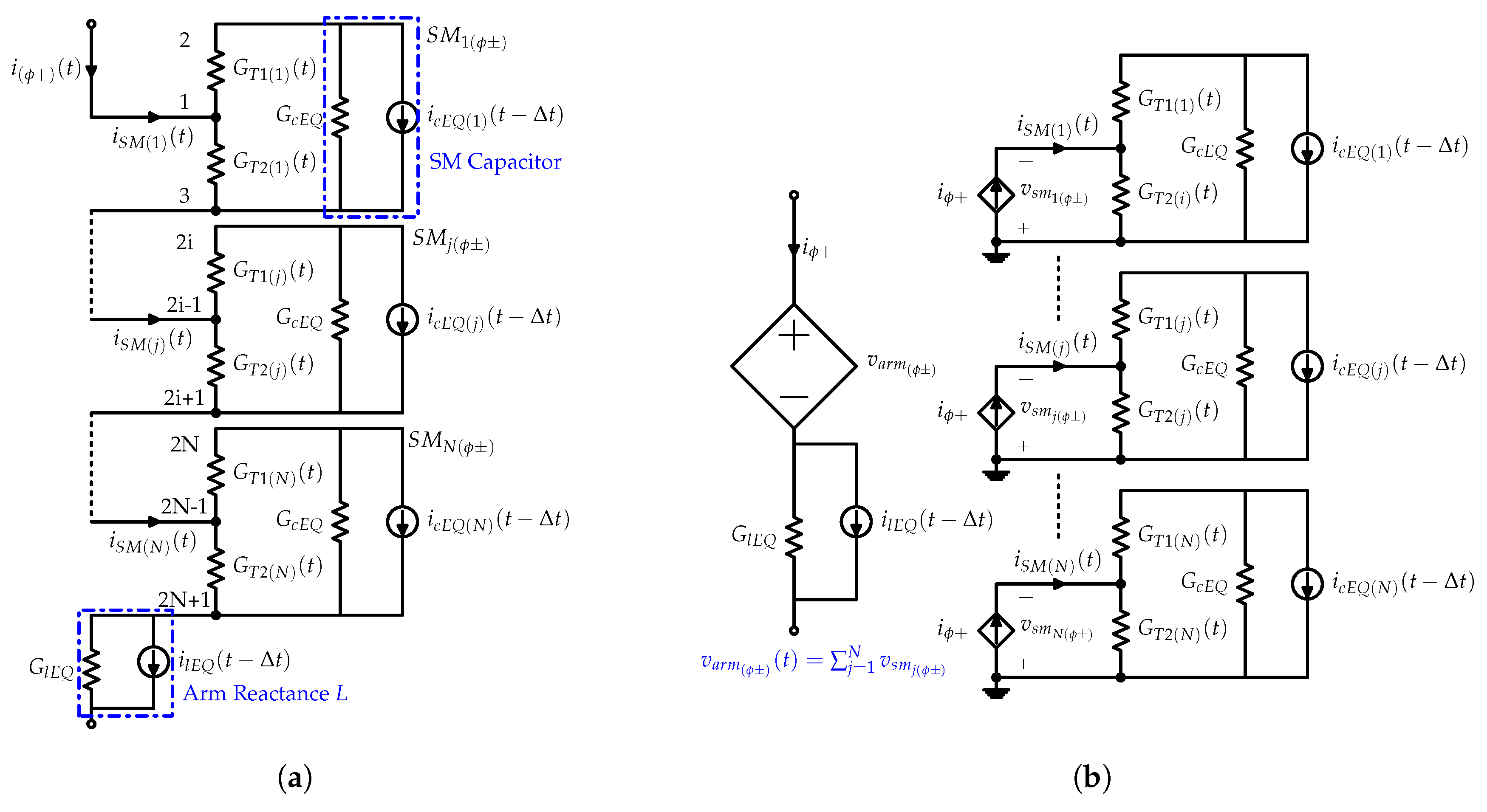
Full physics representation for MMC (Cigré Type 1 [23]) is not computationally realizable. The works in [19,20,89] present the MMC model using the nonlinear IGBT representation (Cigré Type 2 [23]). Based on bi-value resistor representation for semiconductor devices and EMT equivalent representation for lumped elements, an arm for MMC (Cigré Type 3 [23]) is modeled as Figure 4a and is subsequently refereed as the detailed ideal model (DIM).
3.2. MMC Efficient Modeling
Fast and accurate simulations of EMT phenomena require models that capture all of the operating modes of the converter and allow for the natural development of its dynamics. Such efficient yet reasonably accurate models from existing literature include the following.
3.2.1. Isolated Submodule Model
This method as proposed in [18] is identical to the classical modeling approach; however, instead of a unified representation of the entire system, here, the admittance matrix of the system is partitioned into numerous small matrices. That is, each submodule is modeled as a separate subsystem, with its individual system matrix, and the coupling between arms and submodules is reproduced using dependent current and voltage sources. A dependent current source in each submodule mimics its interconnection with the arm, and an arm is replaced by a dependent voltage source, corresponding to the cumulative voltage across all submodules as illustrated in Figure 4b. The work in [90] proposes an enhanced version of this model that renders higher computational efficiency by grouping a number of submodules in each sub-system, while [91] extends this modeling approach to the full-bridge MMC.
This isolated representation for an individual or a group of submodules offers superior computational efficiency of solving numerous small matrices over one large matrix and further enables parallel calculation for each submodule. However, the large number of submodules and frequent switching in the converter imply that even with parallel calculation in this partitioned nodal admittance approach, the resulting model is still not suitable for real-time simulations. Furthermore, the forced decoupling of a coupled system in this model results in an artificial delay in the computation of arm and submodule equivalents. Nevertheless, the continuous nature of arm currents, parallel computation and a small simulation time step mitigate the effect of this computational lag.
3.2.2. Arm Thevenin Equivalent Model
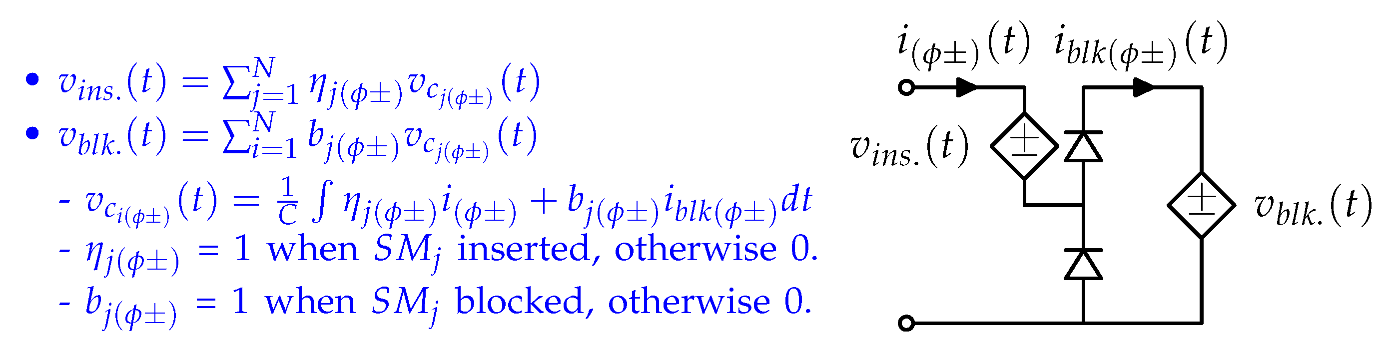
The arm Thevenin equivalent model (EIM) as proposed in [17] utilizes a nested fast and simultaneous solution method to model all submodules in an arm by its Thevenin or Norton equivalent, while internal dynamics of an arm are computed using the linear algebraic relation instead of computationally-intensive matrix operations of the nodal admittance method. Figure 5 illustrates the equivalent representation of N submodules of an arm based on this modeling approach. Here, the Thevenin or Norton equivalent subsystem models inserted and bypassed states of all submodules in the arm, while the blocked state of operation is simulated through additional diodes and switches. The works in [20,89,92,93,94] further investigate this model.
This modeling method drastically reduces the number of nodes in the system. The resolution of the internal dynamics of an arm no longer utilizes computationally-expensive matrix operations, but is modeled by N linear algebraic relations, determined solely by the gate signals and the last time step internal states of the submodules. As a result, the model is suitable for parallel computation, where dedicated processors based on the IGBT gate signals and historical information update the internal and terminal dynamics of individual arms simultaneously, which are concurrently utilized by the main processor modeling the converter and the rest of the system. This combination of parallel computation and reduced computational load makes this model an ideal candidate for real-time simulations [95,96]. However, unlike the nodal analysis method, this representation cannot utilize interpolation for exact tracking of switching instances with a fixed time step solver. As a result, this model, even with a similar IGBT/diode representation, tends to be less accurate as compared to the detailed model representation. Nevertheless, the small time step of simulation implies that the effect is negligible for most of the system dynamics.
3.2.3. Arm Switching Function Model
Unlike EMT models where semiconductor devices are modeled as bi-value resistors or with more detailed representations, the switching function model (SFM) represents the switching operation using binary functions. Such models for MMC are presented in [97,98,99,100]. The works in [97,98,99] utilize the state-space formulation, which is computationally intensive and not suitable for fault studies in an HVDC system, while [100] proposes a generalized switching function model that utilizes the binary function to model the individual operation of submodules with high computational efficiency. The references in [101,102,103,104] extend this modeling approach to allow inherent incorporation of the blocked state of the converter. The works in [102,103] present the implementation of these switching function models using generic blocks from simulation software as illustrated in Figure 6. This representation offers easier implementation compared to the hard-coded Thevenin equivalent representation. Similar to the arm Thevenin equivalent model, the decoupled representation for arms allows for parallel computation in this model and makes it suitable for real-time simulations.
3.2.4. Average Model
Average value modeling further simplifies converter representation by ignoring the switching effects in individual submodules and, similar to switching function models, reproduce the AC and DC terminal dynamics of the converter as controlled current and voltage sources [105]. Based on the assumption of the identical construction of submodules and instantaneous voltage balance control, Refs. [20,101,106,107] represent all N submodules in an arm by an equivalent module. Despite their idealistic assumptions, these models inherently capture internally-stored energies and are suited for large signal analysis of the MMC. These average models are further classified as:
[-20]Moreover, further simplified models for MMC have been proposed in the literature [19,20,21,22,31,107,108,109,110,111,112,113,114,115,116,117,118]. The works in [19,20,21,22] extend the classical average modeling technique for 2/3-level converters [119] to MMC and represent its terminal dynamics using controlled sources; [107,111,112,113,114,120] present enhanced versions of this model that incorporate the blocked state of operation for DC fault simulations and/or consider the effects of distributed submodule capacitor voltage ripple in MMC’s terminal dynamics. Cigré [23] categorizes these extensions of conventional voltage source converter average models to MMC as Types 5 and 6. Furthermore, [115,116] reduce MMC to an equivalent buck-boost circuit. These models represent distributed arm capacitors of MMC for all phases by a lumped capacitor and therefore do not capture the internal dynamics of the converter. For large signal transients, the internal dynamics of the converter determine its terminal dynamics. As a result, these simplified models are merely suitable for power-flow and steady-state studies.
3.3. Model Validation in Literature
Existing literature provides substantial studies for the validation of the equivalent models using simulations and experimental results. The works in [24,51,121] compare the detailed ideal model against experimental prototypes. These studies conclude reporting a high agreement between the detailed model and experimental prototypes. As a result, DIM serves as the standard for the validation of equivalent representations in various studies [17,90,122,123]. The isolated submodule model has been validated in [90,122]. The works in [17,20,109,123,124,125] compare the detailed and EIM models under various transient cases. The continuous variant of EIM has been validated against laboratory prototypes in [110,126]. Similarly, the switching function and average models have been validated against detailed models or EIM in the literature [19,20,100,101,106,107].
However, not all of the studies simulate all operating states of the converter, and existing literature lacks an independent collective comparison. Therefore, the following section is dedicated to a comprehensive simulation comparison of the select EIM, SFM and AVM models.
4. Model Comparison
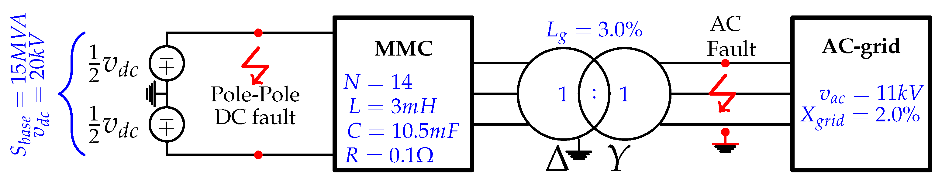
This section compares the presented equivalent models in terms of accuracy and computational speed under steady-state and transient conditions using the system illustrated in Figure 7. The system mimics a modular multilevel converter system coupling an HVDC link and a strong AC grid. For the validation of the computational efficiency and accuracy of the modeling techniques, the detailed ideal model, the Thevenin equivalent model [17], the switching function model (SFM) [17] and the average value model [101], described in previous sections, are simulated. The reason for simulating just these models is the diversity in their solution methods, while the rest of the presented models can be categorized into one of these four representations and are expected to be simulated with a similar order of accuracy and computational speed. The detailed ideal model, the classical EMT representation with bi-value resistor model for semiconductor devices, serves as the benchmark for the accuracy and computational speed of the three efficient equivalent models.
The models are simulated on a 48-core Windows Server 2012 with PSCAD Version using the GFortan compiler with a time step of 10 s [49,127]. The prime motivation for the selection of PSCAD/EMTDC as the choice of simulation software is its wide use in industry and academia [18,38,49,100,123] for the simulation of the HVDC grid system. However, constrained by the restriction on the maximum number of nodes (200) of the educational license of PSCAD/EMTDC, the maximum number of submodules per arm in these simulations is restricted to 14.
The control scheme for the converter system utilizes vector control to regulate power exchange with the grid. For arm level modulation, uncompensated modulation with circulating current suppression control [38] is employed, together with nearest level control with the capacitor voltage rank-based method for the module level modulation.
4.1. Model Accuracy
To investigate the accuracy of the equivalent models, internal and external dynamics of the converter under steady-state and transient conditions are validated against the detailed model. The transients associated with the power converter can be categorized as control system set-point changes, over/under voltage on AC-DC sides and internal faults. Equivalent models investigated here do not allow access to internal components and hence cannot simulate internal faults. To address the remaining transient cases, the paper examines six different scenarios, i.e., real/reactive power reversal at the AC side of the converter, single line/three phase to ground faults at the converter transformer, terminal pole to pole and pole to ground DC faults. The performance of the equivalent models under these extreme transient conditions is representative of the maximum error in equivalent idealized representations, and dynamics under any other scenarios are expected to yield similar, if not better accuracy.
The MMC system being simulated here is restricted to 14 submodules per arm, while for HVDC applications, N is in the order of 100s. Nevertheless, the number of submodules scales with power and voltage ratings and the energy stored per submodule is generally of the same order, and there are no operational differences. As a result, conclusions drawn about the accuracy of the equivalent models are expected to be independent of N.
The simulation results in the following sections present the dynamics before, during and after the transient conditions and the absolute error relative to the detailed ideal model. Furthermore, the overall accuracy of the models is quantified using the normalized mean absolute error () given by Equation (8).
where, is the value of simulated dynamic for the model under consideration and K is the number of simulation points in the interval under investigation.
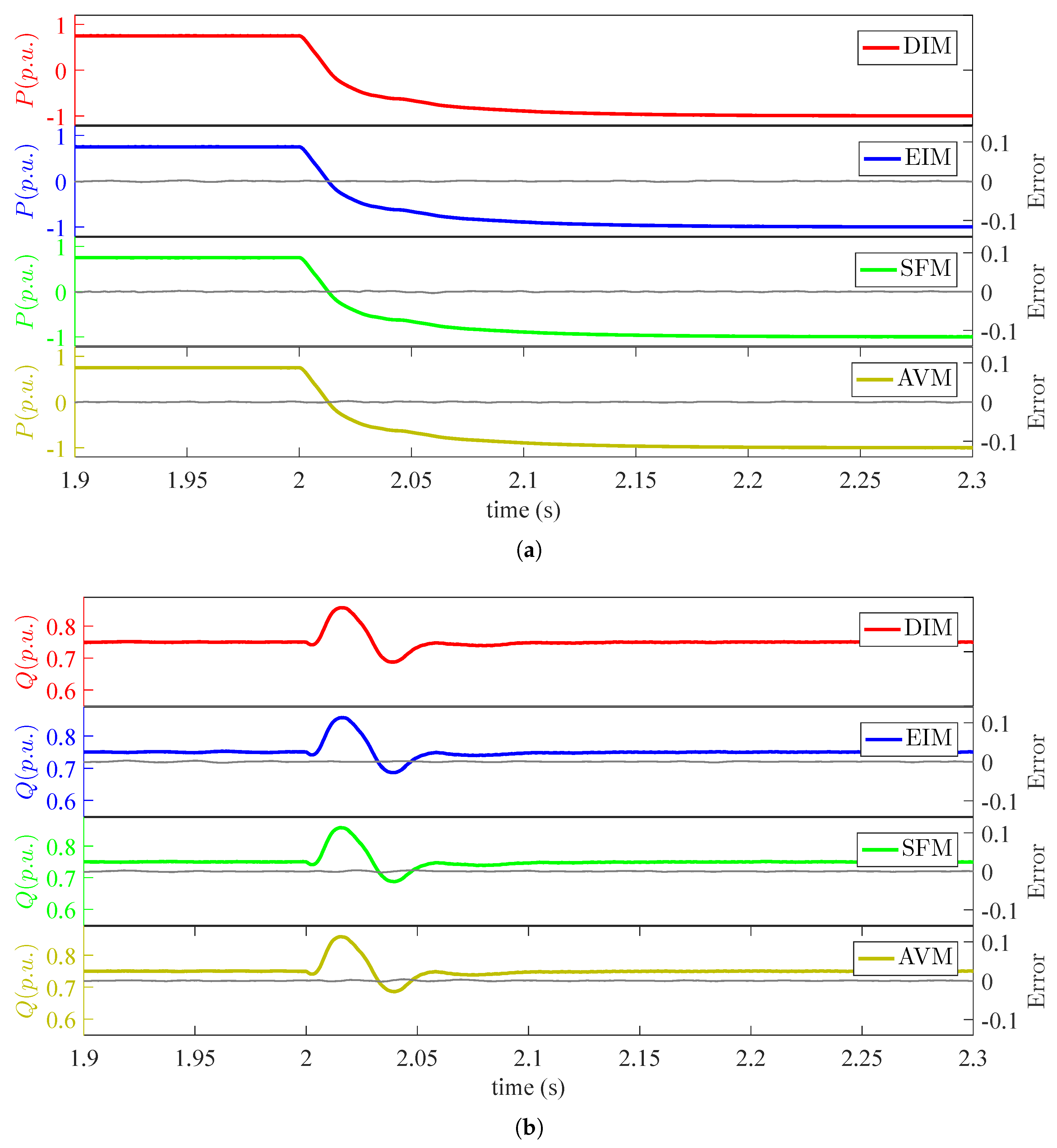
4.1.1. Power Flow Reversals
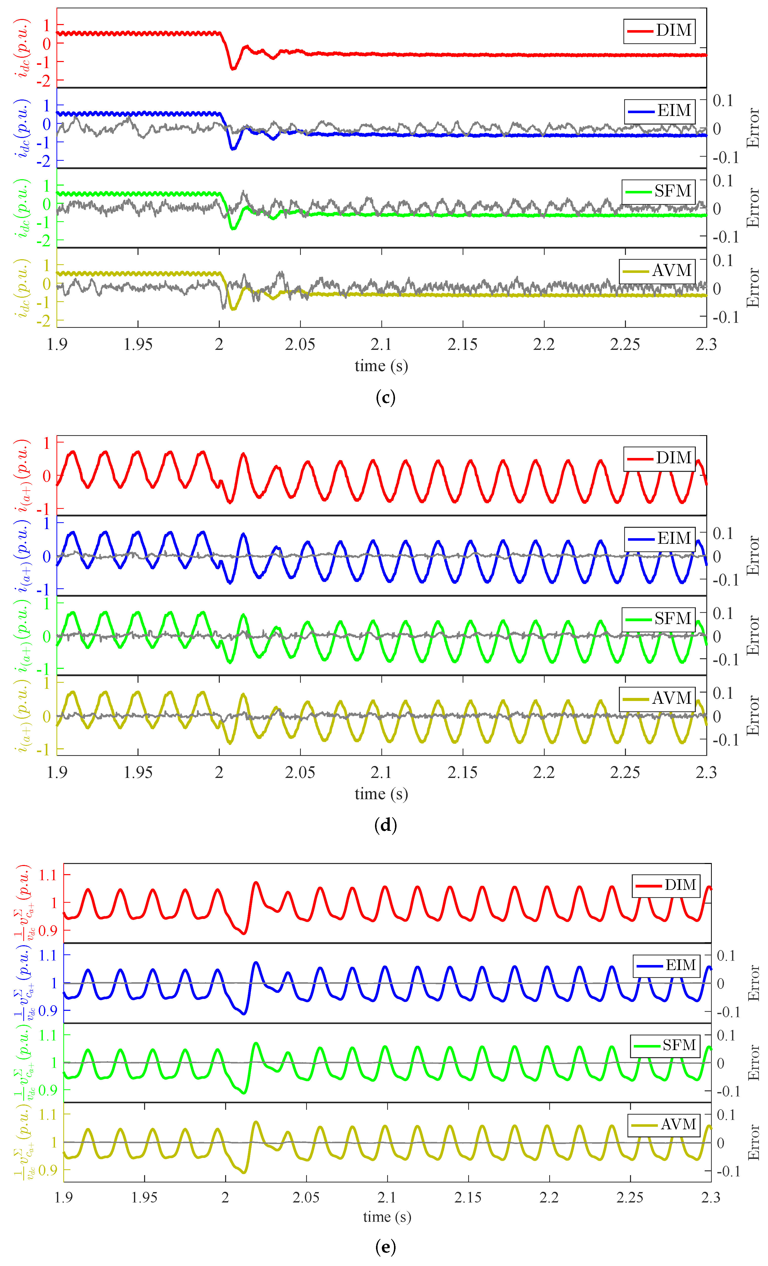
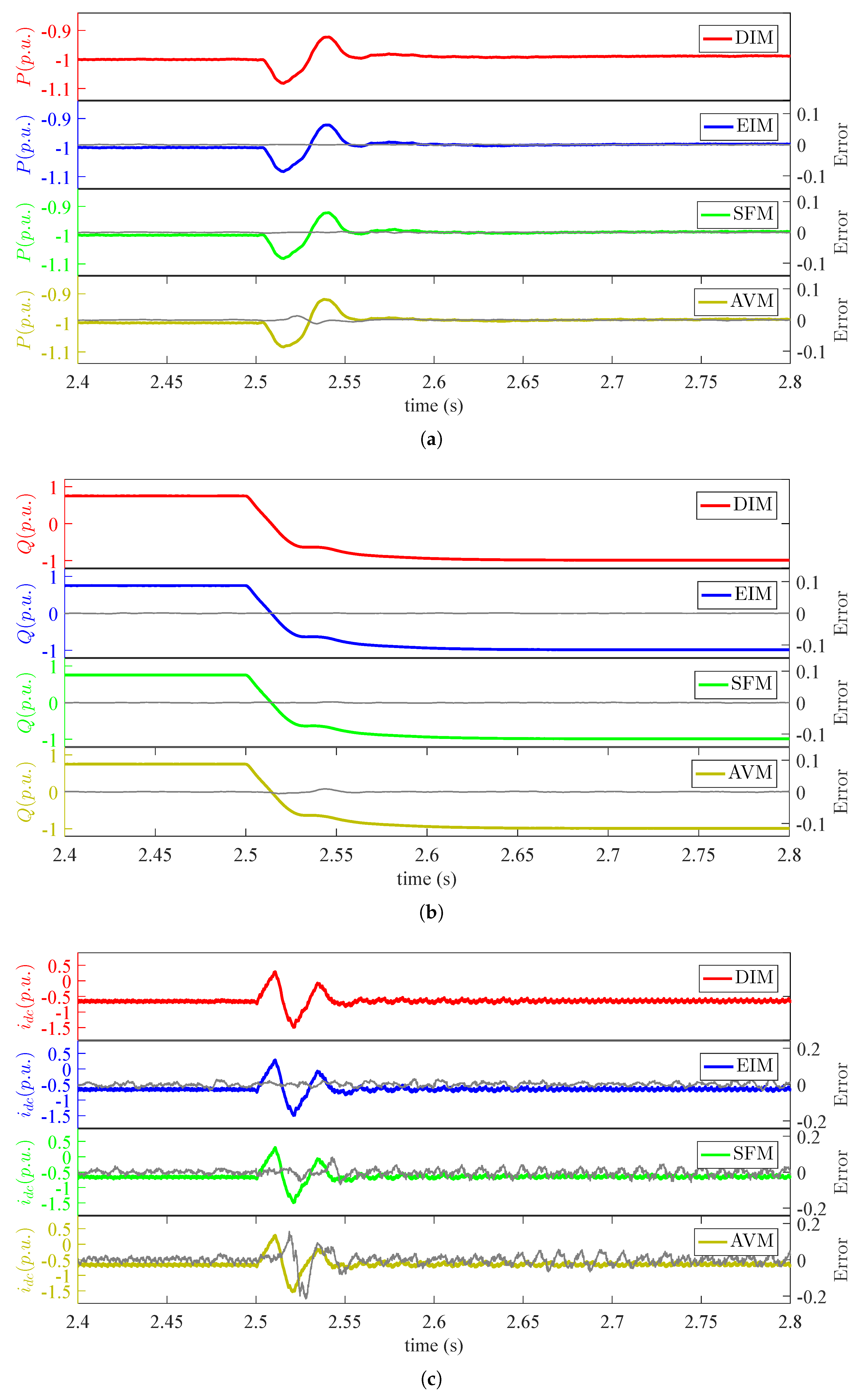
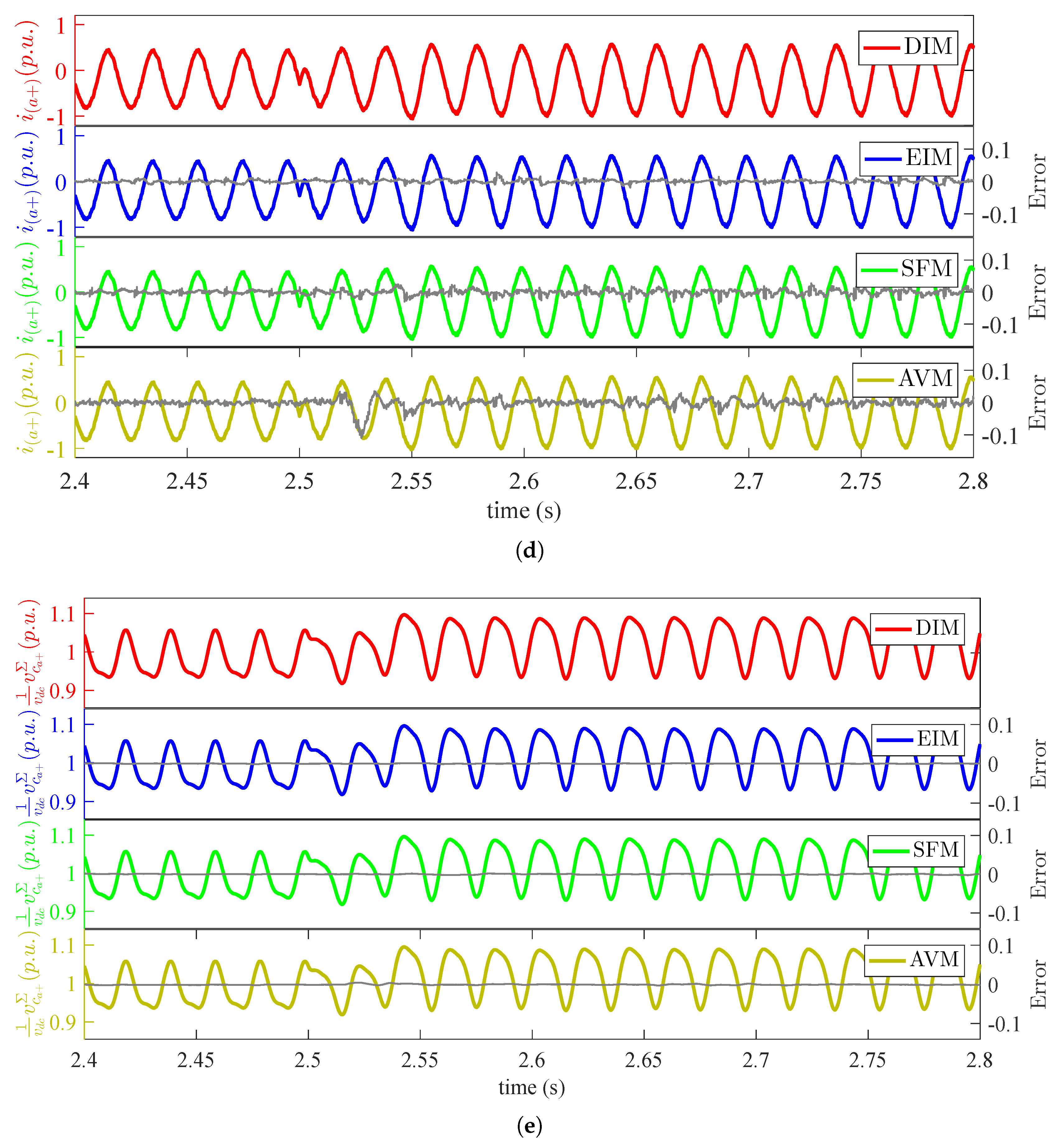
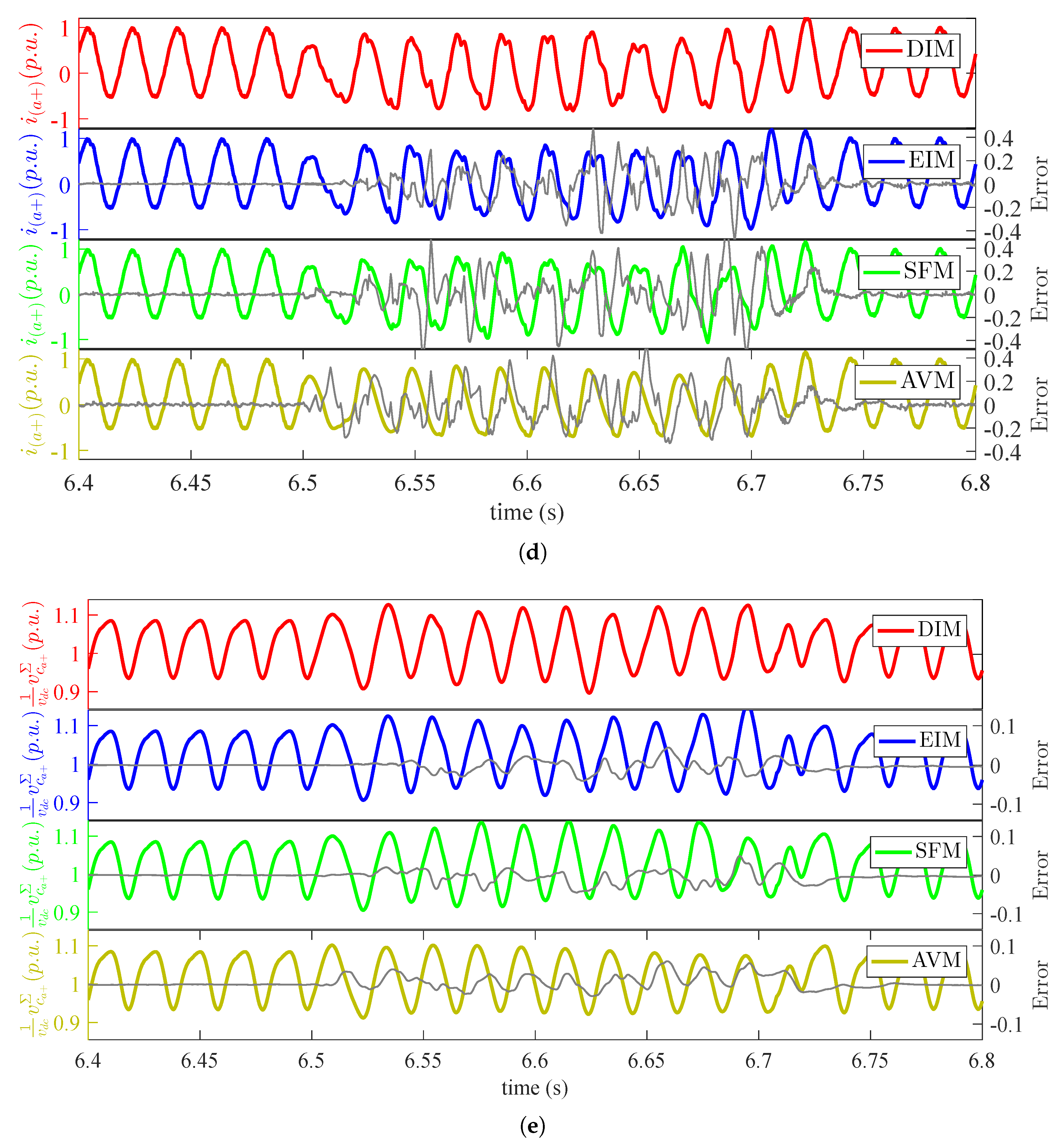
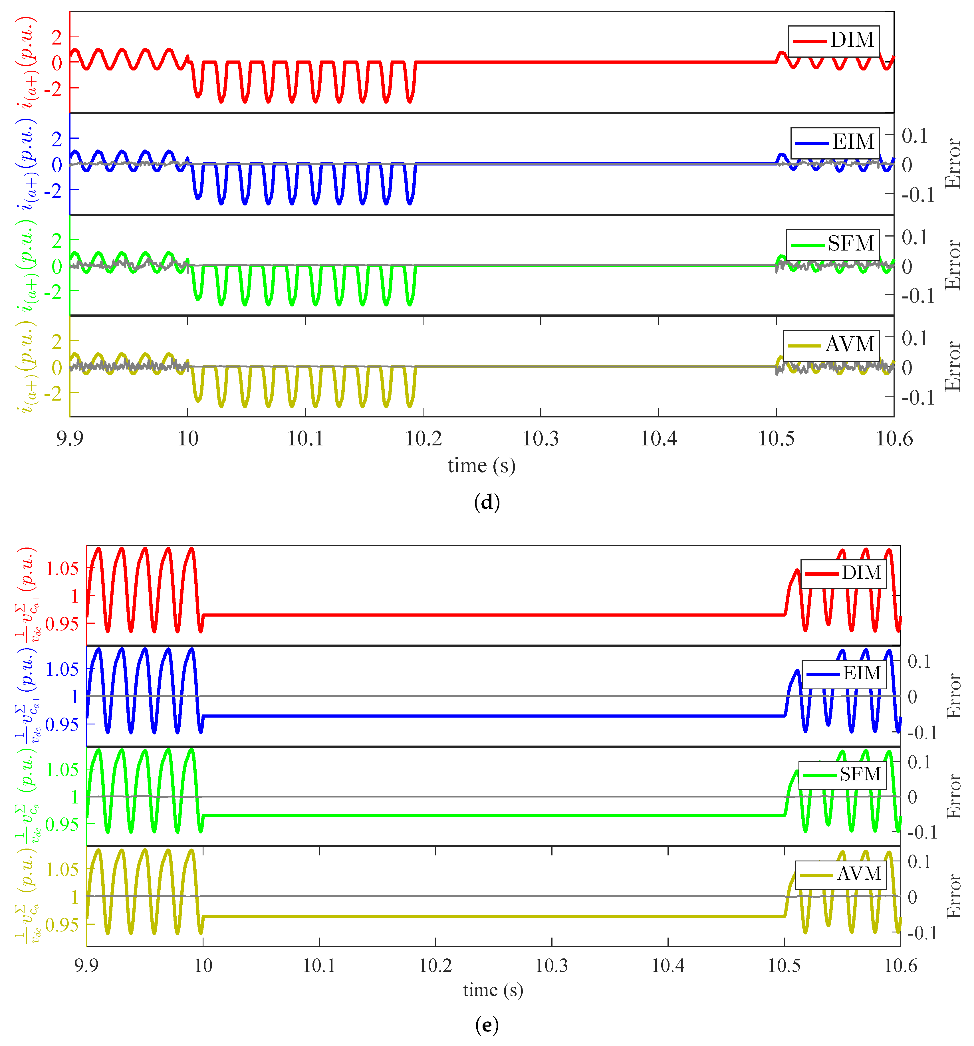
To observe the four-quadrant capability of modular multilevel converters and the accuracy of the equivalent models for power-flow transients, real and reactive power reversal scenarios are simulated, and the results are presented in Figure 8 and Figure 9. The simulation reproduces the dynamics of a converter undergoing a step change in a set point of P, real power exchange with the AC grid, from 0.75 p.u.– −1.0 p.u. at s, and the step change in the reference point of Q, reactive power exchange with the AC grid, from 0.75 p.u.–−1.0 p.u. at s. Terminal dynamics, i.e., real power, reactive power and DC current, are presented in Figure 8 and Figure 9a–c, respectively; while internal dynamics, i.e., upper arm current and cumulative capacitor voltage, are illustrated in Figure 8 and Figure 9d,e, respectively. In both scenarios, as seen from Figure 8 and Figure 9a,b, the converter reaches the desired real/reactive power set-point in a short duration without overshoot or oscillations.
These results confirm that EIM, SFM and AVM capture the dynamics of the converter under changing power-flow conditions with high accuracy and normalized mean absolute error of less than , and , respectively, against the DIM.
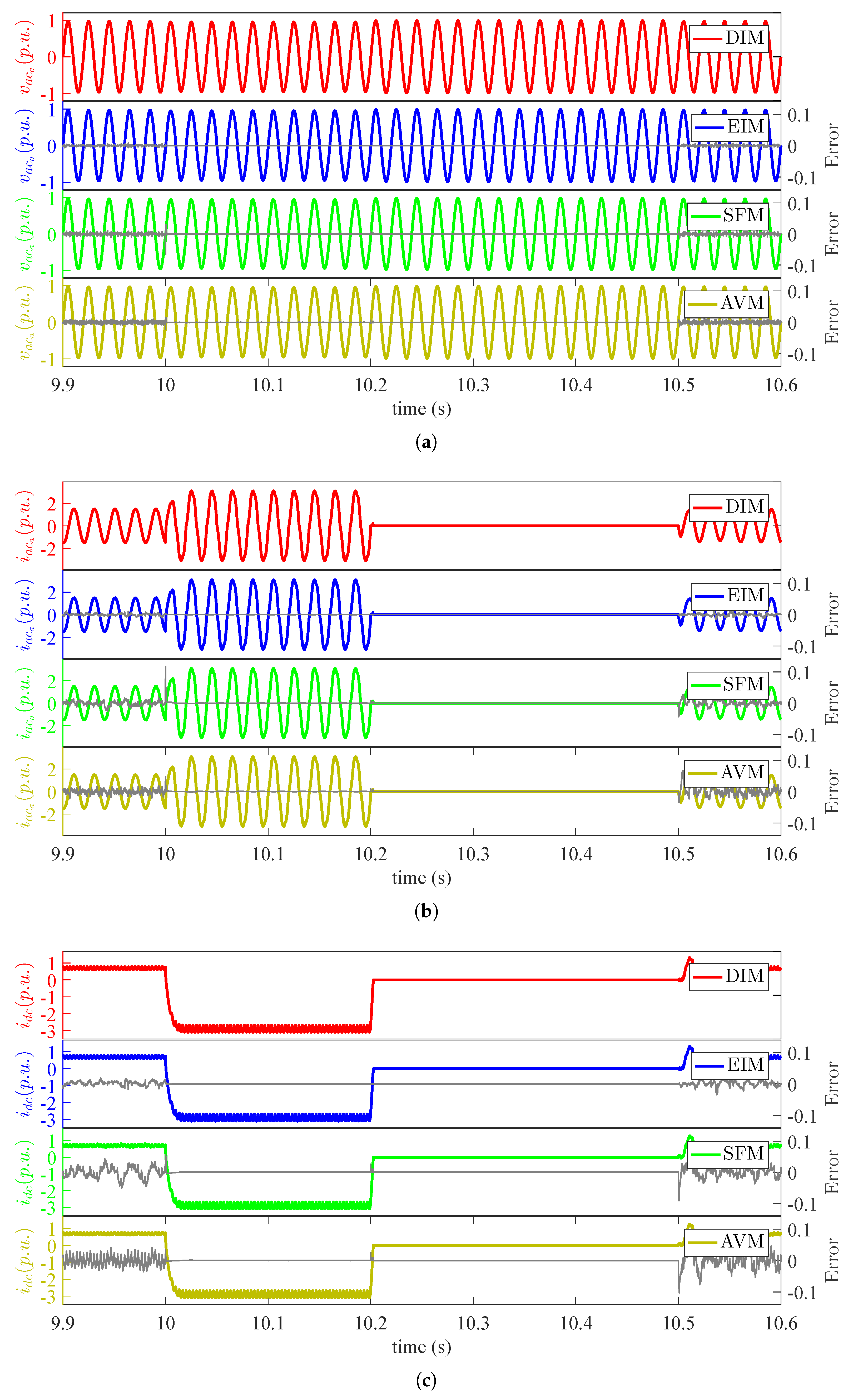
4.1.2. AC Side Faults
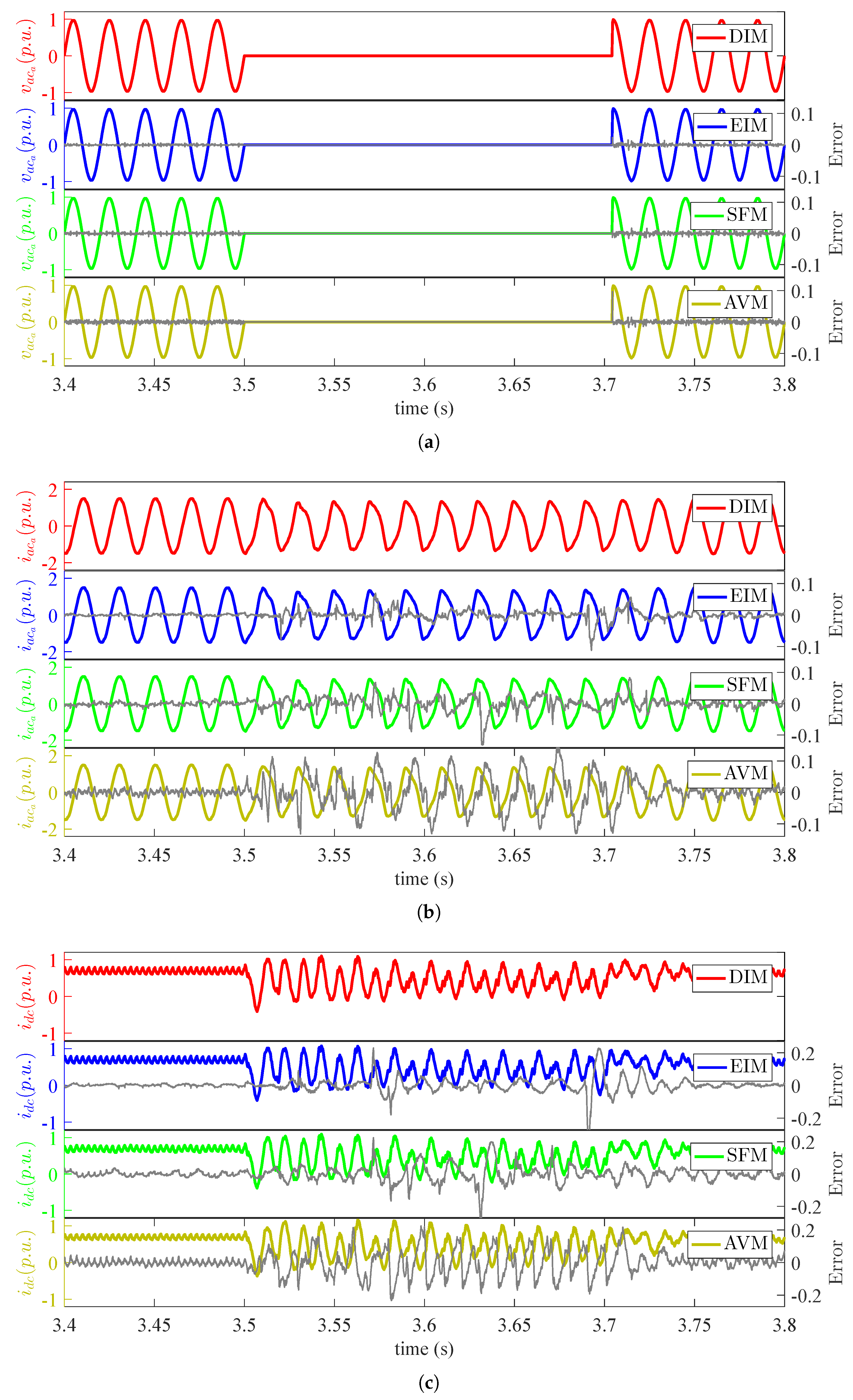
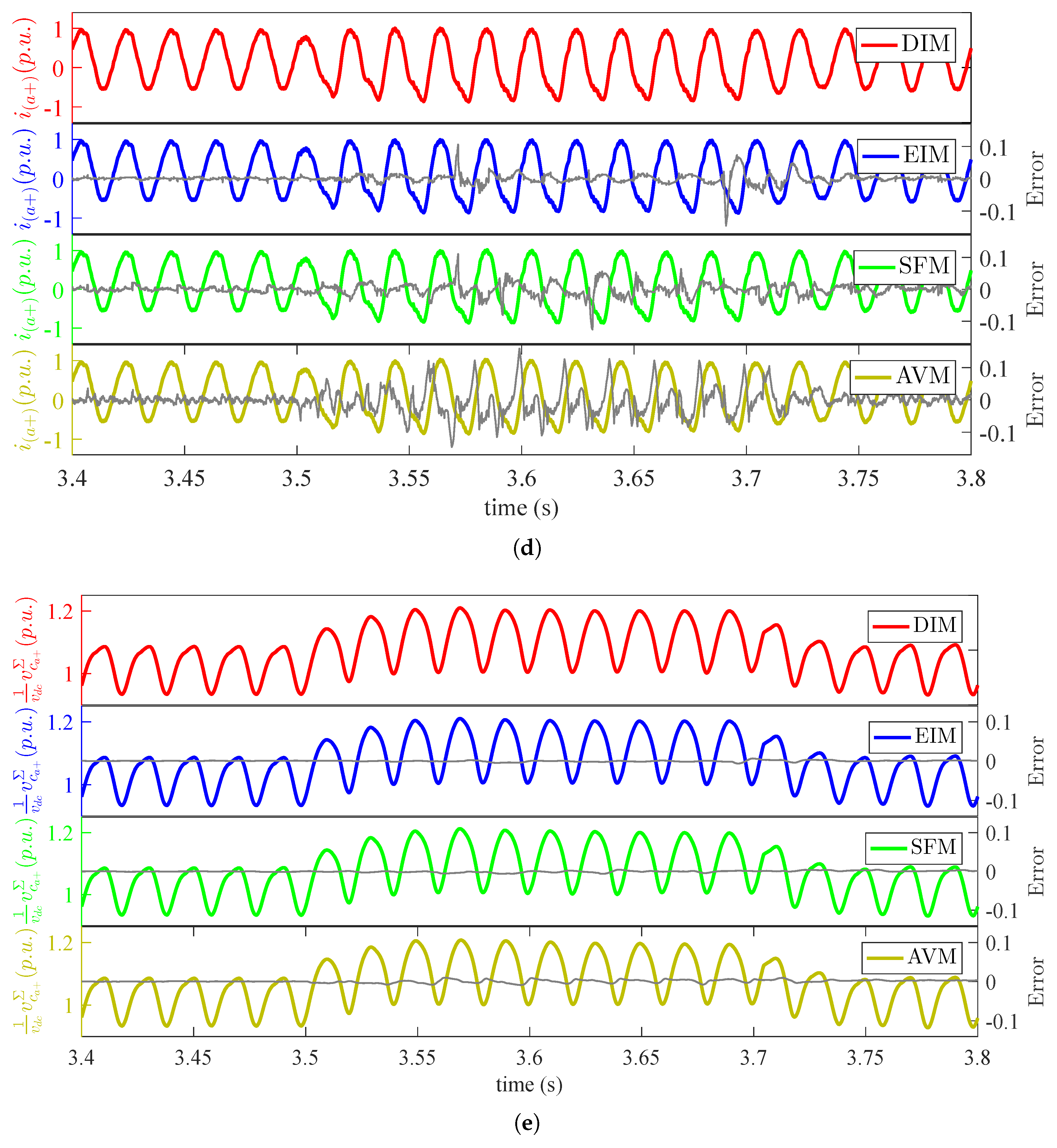
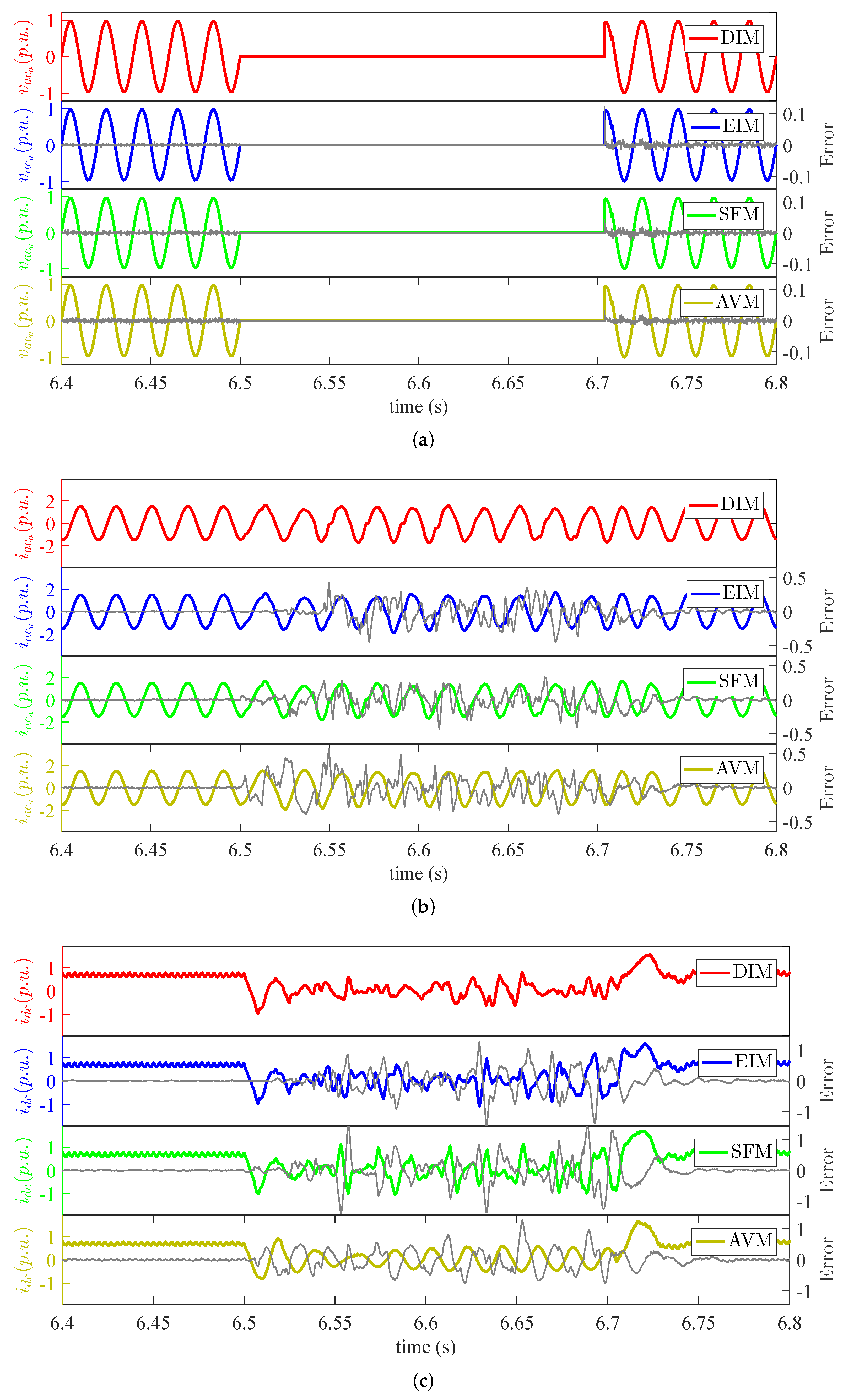
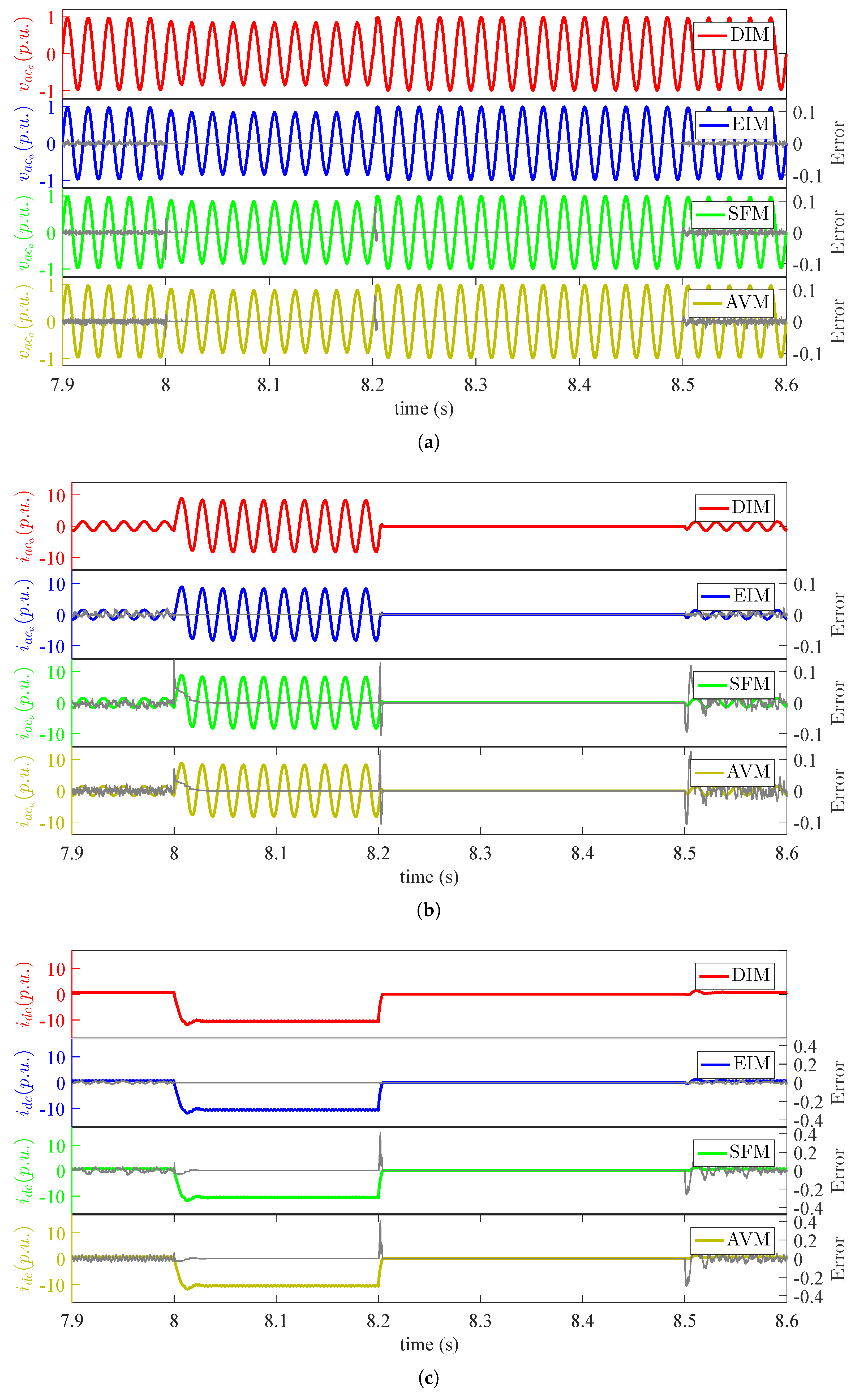
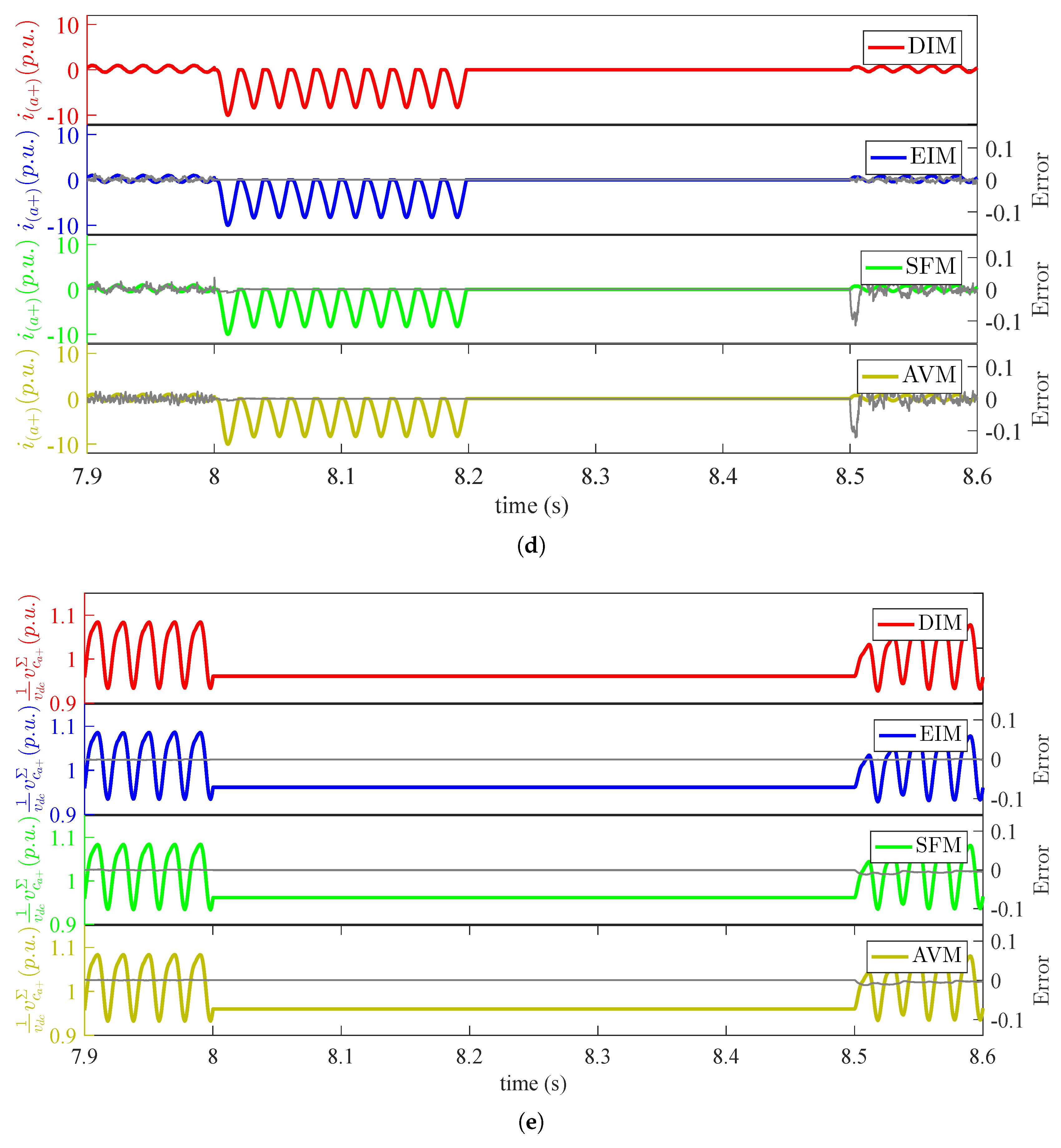
For verification of the presented models under the severe transient condition at the AC side, a single line to ground fault and a three phase to ground fault, both lasting for 200 ms through a negligibly small resistance (0.005 Ω) at the Y terminal of the transformer, are simulated at s and s, respectively. Throughout the duration of fault, the system and its control operation are kept unchanged. Terminal dynamics, i.e., AC voltage, current and DC current, are presented in Figure 10 and Figure 11a–c, respectively; while internal dynamics, i.e., upper arm current and cumulative capacitor voltage, are illustrated in Figure 10 and Figure 11d,e, respectively. These results confirm that EIM, SFM and AVM capture the dynamics of the converter under the single-line to ground AC fault condition with high accuracy and normalized mean absolute error of less than , and , respectively, against the DIM. Errors are significantly high for the three phase faults to ground, but the peak values and envelop of dynamics accurately mimic the detailed model, making equivalent models even suitable for the extreme AC-fault studies.
4.1.3. DC Side Faults
To investigate the modeling of the blocked state of operation and the transients under severe transients on the DC side, a 200-ms pole-pole and pole to ground DC fault are simulated at s and s, respectively. The submodules are blocked as the DC side voltage drops below of its nominal value and unblocked with a delay of 300 ms after the DC-voltage regains its nominal voltage. Terminal dynamics, i.e., AC voltage, current and DC current, are presented in Figure 12 and Figure 13a–c, respectively; while upper arm current and cumulative capacitor voltage are illustrated in Figure 12 and Figure 13d,e, respectively. These results also confirm that EIM, SFM and AVM accurately capture the dynamics of the converter under DC fault conditions with normalized mean absolute error of less than , and , respectively, against the DIM.
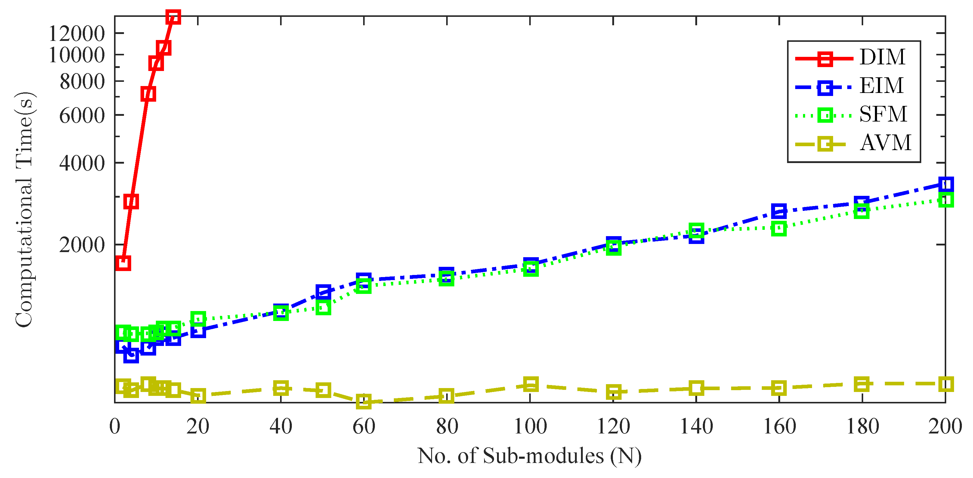
4.2. Model Computational Load
For comparison of the relative computational efficiency of the presented equivalent models, a 12-s simulation of the system subject to numerous transient conditions was conducted. For this simulation, N was varied between two and 200, and the execution times for the models are presented in Figure 14. These results confirm the computational efficiency of the EIM, SFM and AVM against DIM. Already with 14 submodules per arm, SFM and EIM offer a model with 20-times higher computational speed against the DIM; while AVM has a fixed computational load irrespective of N.
In summary, these simulation results validate the precision of the presented EIM, SFM and AVM in replicating a detailed model with high accuracy. The Thevenin equivalent and switching function models are shown to have high computational speed with little loss in accuracy, while the average model with a constant computational load irrespective of the number of submodule offers very high computational efficiency with a compromise on internal dynamic simulation of the converter. Table 4 summarizes the models and their prospective modeling applications.
5. Discussion and Conclusions
With a global shift towards renewable energy, MMC with its superior design is becoming the technology of choice for point to point and multi-terminal HVDC systems. This converter topology requires an elaborate control and poses a computational challenge to classical simulation methods, which is the subject of interest in several recent studies. The operation of grid-connected converter requires multi-tier control and modulation schemes, which are classified and discussed in this paper.
The specific objective is to present an overview of MMC models from the literature that are suitable for EMT studies. All of the models discussed reproduce all operating states of the converter and capture its internal and external dynamics under stationary and transient conditions. These models vary in accuracy, as well as in the computational load. HVDC and converter studies involve analyses at the component, system or network levels with varying requirements for computational efficacy and efficiency, making each model a best fit to the simulation application as discussed below:
- Detailed models are the next best thing to prototype setups and provide the highest accuracy among all simulation models. These models subject to the accuracy of semiconductor representation, provide precise analyses of switching characteristics and are suitable for studies at the component level such as component optimization, electromagnetic compatibility (EMC) validation, switching loss estimation, etc.
- For system-level studies, where switching events can be modeled as instantaneous events, isolated submodule, Thevenin equivalent and switching function models offer a computationally-efficient representation. These modeling approaches are suitable for the simulation of the large signal behavior of the converter system and faster submodule level control and modulation schemes. The isolated submodule model allows access to individual submodules and is suited for the simulation of internal faults, while the Thevenin equivalent and switching function models with parallel computation are appropriate for real-time simulations.
- Lastly, for the network-level studies, where terminal characteristics are of prime interest, average models with an accurate description of terminal dynamics provide an efficient representation. These models are further appropriate for the design and validation of the converter control and arm modulation schemes.
In short, it is concluded that the arm Thevenin equivalent and the switching function models that individually represent all submodules can precisely replace a detailed model for system-level studies of the converter. These models with parallel computation capabilities are suitable for real-time simulations; whereas the average value model with a constant computational load and accurate terminal characteristics is suited for network-level studies.
Acknowledgments
The authors would like to acknowledge and thank Jon Are Suul for his valuable feedback and contribution to the paper. Part of this work has been funded in the framework of the joint programming initiative ERA-Net Smart Grids Plus, with support from the European Union’s Horizon 2020 research and innovation program and the Research Council of Norway through the CloudGrid project.
Author Contributions
Review analysis and simulations are performed by the first author under the scientific supervision of the second author.
Conflicts of Interest
The authors declare no conflict of interest.
Nomenclature
Angular frequency of AC current. | |
| N | Number of submodules in an arm. |
| L | Arm reactance. |
Converter transformer reactance. | |
| R | Arm resistance. |
| C | Submodule’s capacitance. |
Submodule’s capacitor voltage. | |
Submodule’s terminal voltage and current. | |
Phase leg of converter. | |
| j | Position of submodule in an arm. |
Equivalent average cumulative capacitor voltage and current for all SMs of an arm. | |
Insertion Index for an arm. | |
Voltage inserted in an arm. | |
Arm current. | |
Equivalent internal e.m.f and impedance of MMC for the AC side. | |
Circulating current in a phase leg. | |
Voltage drop in an arm due to circulating current. | |
Voltage modulation index. | |
AC phase current. | |
DC side voltage. | |
DC side current. | |
Phase difference between AC voltages. | |
Normalized mean absolute error. | |
| K | Simulation points in the interval. |
References
- Lesnicar, A.; Marquardt, R. An innovative modular multilevel converter topology suitable for a wide power range. In Proceedings of the 2003 IEEE Bologna Power Tech Conference Proceedings, Bologna, Italy, 23–26 June 2003; Volume 3, p. 6. [Google Scholar]
- Marquardt, R.; Lesnicar, A. New concept for high voltage-modular multilevel converter. In Proceedings of the Power Electronics Specialists Conference PESC ’04, Aachen, Germany, 20–25 June 2004. [Google Scholar]
- Marquardt, R.; Lesnicar, A. A new modular voltage source inverter topology. In Proceedings of the European Power Electronics Conference (EPE), Toulouse, France, 2–4 September 2003; Volume 3, pp. 2–4. [Google Scholar]
- Marquardt, R.; Lesnicar, A.; Hildinger, J. Modulares stromrichterkonzept für netzkupplungsanwendung bei hohen spannungen. Available online: https://www.unibw.de/eit62/forsch/SP/M2LC/m2lcveroef/anle2002bdnau (accessed on 29 June 2017).
- Knaak, H.J. Modular multilevel converters and HVDC/FACTS: A success story. In Proceedings of the 14th European Conference on Power Electronics and Applications (EPE 2011), Birmingham, United Kingdom, 30 August–1 September 2011. [Google Scholar]
- Friedrich, K. Modern HVDC PLUS application of VSC in Modular Multilevel Converter topology. In Proceedings of the 2010 IEEE International Symposium on Industrial Electronics, Bari, Italy, 4–7 July 2010; pp. 3807–3810. [Google Scholar]
- Dorn, J.; Huang, H.; Retzmann, D. Novel voltage-sourced converters for HVDC and FACTS applications. In Proceedings of the Cigré Symposium, Osaka, Japan, 1–4 November 2007. [Google Scholar]
- Dorn, J.; Huang, H.; Retzmann, D. A new multilevel voltage-sourced converter topology for HVDC applications. In Proceedings of the Cigré Session, Paris, France, 24–29 August 2008; pp. 1–8. [Google Scholar]
- Saeedifard, M.; Iravani, R. Dynamic performance of a modular multilevel Back-to-Back HVDC system. IEEE Trans. Power Deliv. 2010, 25, 2903–2912. [Google Scholar] [CrossRef]
- Allebrod, S.; Hamerski, R.; Marquardt, R. New transformerless, scalable modular multilevel converters for HVDC-transmission. In Proceedings of the IEEE Power Electronics Specialists Conference, Rhodes, Greece, 5–19 June 2008; pp. 174–179. [Google Scholar]
- Gerdes, J. Siemens Debuts HVDC PLUS with San Francisco’s Trans Bay Cable. Available online: http://www.energy.siemens.com/hq/pool/hq/energy-topics/living-energy/issue-5/LivingEnergy_05_hvdc.pdf (accessed on 6 February 2016).
- Siemens Puts Converter Stations of HVDC Link Between France and Spain Into Operation. Available online: https://www.siemens.com/press/PR2015040185EMEN (accessed on 6 February 2016).
- Abildgaard, E.N.; Molinas, M. Modelling and control of the modular multilevel converter (MMC). Energy Procedia 2012, 20, 227–236. [Google Scholar] [CrossRef]
- Marquardt, R. Modular Multilevel Converter: An universal concept for HVDC-Networks and extended DC-Bus-applications. In Proceedings of the IEEE International Power Electronics Conference, Sapporo, Japan, 21–24 June 2010; pp. 502–507. [Google Scholar]
- Gemmell, B.; Dorn, J.; Retzmann, D.; Soerangr, D. Prospects of multilevel VSC technologies for power transmission. In Proceedings of the IEEE/PES Transmission and Distribution Conference and Exposition, Chicago, USA, 21–24 April 2008; pp. 1–16. [Google Scholar]
- Teeuwsen, S.P. Simplified dynamic model of a voltage-sourced converter with modular multilevel converter design. In Proceedings of the IEEE/PES Power Systems Conference and Exposition, Seattle, WA, USA, 15–18 March 2009; pp. 1–6. [Google Scholar]
- Gnanarathna, U.N.; Gole, A.M.; Jayasinghe, R.P. Efficient Modeling of Modular Multilevel HVDC Converters (MMC) on Electromagnetic Transient Simulation Programs. IEEE Trans. Power Deliv. 2011, 26, 316–324. [Google Scholar] [CrossRef]
- Xu, J.; Zhao, C.; Liu, W.; Guo, C. Accelerated model of modular multilevel converters in PSCAD/EMTDC. IEEE Trans. Power Deliv. 2013, 28, 129–136. [Google Scholar] [CrossRef]
- Saad, H.; Peralta, J.; Dennetiere, S.; Mahseredjian, J.; Jatskevich, J.; Martinez, J.A.; Davoudi, A.; Saeedifard, M.; Sood, V.; Wang, X.; et al. Dynamic Averaged and Simplified Models for MMC-Based HVDC Transmission Systems. IEEE Trans. Power Deliv. 2013, 28, 1723–1730. [Google Scholar] [CrossRef]
- Saad, H.; Dennetière, S.; Mahseredjian, J.; Delarue, P.; Guillaud, X.; Peralta, J.; Nguefeu, S. Modular multilevel converter models for electromagnetic transients. IEEE Trans. Power Deliv. 2014, 29, 1481–1489. [Google Scholar] [CrossRef]
- Peralta, J.; Saad, H.; Dennetiere, S.; Mahseredjian, J. Dynamic performance of average-value models for multi-terminal VSC-HVDC systems. In Proceedings of the IEEE Power and Energy Society General Meeting, San Diego, CA, USA, 22–26 July 2012; pp. 1–8. [Google Scholar]
- Peralta, J.; Saad, H.; Dennetière, S.; Mahseredjian, J.; Nguefeu, S. Detailed and Averaged Models for a 401-Level MMC–HVDC System. IEEE Trans. Power Deliv. 2012, 27, 1501–1508. [Google Scholar] [CrossRef]
- Cigre, W.G. WG B4-57 Guide for the Development of Models for HVDC Converters in a HVDC Grid; Tech. Broch: Pairs, France, 2014. [Google Scholar]
- Hagiwara, M.; Akagi, H. PWM control and experiment of modular multilevel converters. In Proceedings of the IEEE Power Electronics Specialists Conference, Rhodes, Greece, 15–19 June 2008; pp. 154–161. [Google Scholar]
- Akagi, H. Classification, terminology, and application of the modular multilevel cascade converter (MMCC). IEEE Trans. Power Electron. 2011, 26, 3119–3130. [Google Scholar] [CrossRef]
- Akagi, H. Multilevel converters: Fundamental circuits and systems. Proc. IEEE 2017, 99, 1–18. [Google Scholar] [CrossRef]
- Debnath, S.; Debnath, S.; Qin, J.; Bahrani, B.; Saeedifard, M.; Barbosa, P. Operation, control, and applications of the modular multilevel converter: A review. IEEE Trans. Power Electron. 2015, 30, 37–53. [Google Scholar] [CrossRef]
- Spahic, E.; Schettler, F.; Varma, D.; Dorn, J. Impact of the DC technology on transmission grids. In Proceedings of the 11th IET International Conference on AC and DC Power Transmission, Birmingham, UK, 10–12 February 2015; pp. 1–7. [Google Scholar]
- Jones, P.; Davidson, C. Calculation of power losses for MMC-based VSC HVDC stations. In Proceedings of the 15th European Conference on Power Electronics and Applications (EPE), Lille, France, 2–6 September 2013; pp. 1–10. [Google Scholar]
- Davidson, C.; Trainer, D. Innovative concepts for hybrid multi-level converters for HVDC power transmission. In Proceedings of the 9th IET International Conference on AC and DC Power Transmission, London, UK, 19–21 October 2010; pp. 1–5. [Google Scholar]
- Antonopoulos, A.; Angquist, L.; Nee, H.P. On dynamics and voltage control of the Modular Multilevel Converter. In Proceedings of the 13th European Conference on Power Electronics and Applications, Barcelona, Spain, 8–10 September 2009; pp. 1–10. [Google Scholar]
- Ilves, K.; Antonopoulos, A.; Norrga, S.; Nee, H.P. Steady-State analysis of interaction between harmonic components of arm and line quantities of modular multilevel converters. IEEE Trans. Power Electron. 2012, 27, 57–68. [Google Scholar] [CrossRef]
- Tu, Q.-R.; Xu, Z.; Zheng, X.; Guan, M.-Y. Mechanism analysis on the circulating current in modular multilevel converter based HVDC. High Volt. Eng. 2010, 2, 45. [Google Scholar]
- Zhao, F.; Xiao, G.; Liu, M.; Su, S.; Yang, D.; Li, F. Accurate mathematical steady-state models of arm and line harmonic characteristics for modular multilevel converter. In Proceedings of the 2017 IEEE Applied Power Electronics Conference and Exposition (APEC), Tampa, FL, USA, 26–30 March 2017; pp. 3479–3485. [Google Scholar]
- Sood, V.; Patel, H. Comparison between direct and vector control strategy for VSC-HVDC system in EMTP-RV. In Proceedings of the 2010 Joint International Conference on Power Electronics, Drives and Energy Systems and 2010 Power India, New Delhi, India, 20–23 December 2010; pp. 1–6. [Google Scholar]
- Bajracharya, C.; Molinas, M.; Suul, J.A.; Undeland, T.M. Understanding of tuning techniques of converter controllers for VSC-HVDC. In Proceedings of the Nordic Workshop on Power and Industrial Electronics (NORPIE/2008), Espoo, Finland, 9–11 June 2008. [Google Scholar]
- Zhang, L.; Harnefors, L.; Nee, H.P. Modeling and control of VSC-HVDC links connected to island systems. IEEE Trans. Power Syst. 2011, 26, 783–793. [Google Scholar] [CrossRef]
- Tu, Q.; Xu, Z.; Zhang, J. Circulating current suppressing controller in modular multilevel converter. In Proceedings of the 36th Annual Conference on IEEE Industrial Electronics Society, Glendale, CA, USA, 7–10 November 2010; pp. 3198–3202. [Google Scholar]
- He, L.; Zhang, K.; Xiong, J.; Fan, S. A repetitive control scheme for harmonic suppression of circulating current in modular multilevel converters. IEEE Trans. Power Electron. 2015, 30, 471–481. [Google Scholar] [CrossRef]
- Bahrani, B.; Debnath, S.; Saeedifard, M. Circulating current suppression of the modular multilevel converter in a Double-Frequency rotating reference frame. IEEE Trans. Power Electron. 2016, 31, 783–792. [Google Scholar] [CrossRef]
- Ben-Brahim, L.; Gastli, A.; Trabelsi, M.; Ghazi, K.A.; Houchati, M.; Abu-Rub, H. Modular multilevel converter circulating current reduction using model predictive control. IEEE Trans. Ind. Electron. 2016, 63, 3857–3866. [Google Scholar] [CrossRef]
- Konstantinou, G.; Pou, J.; Ceballos, S.; Picas, R.; Zaragoza, J.; Agelidis, V. Control of circulating currents in modular multilevel converters through redundant voltage levels. IEEE Trans. Power Electron. 2016, 31, 7761–7769. [Google Scholar] [CrossRef]
- Moranchel, M.; Konstantinou, G.; Pou, J.; Ceballos, S.; Picas, R.; Zaragoza, J.; Agelidis, V.G. Circulating current elimination in Modular Multilevel Converter with resonant controllers. In Proceedings of the 2016 IEEE 7th International Symposium on Power Electronics for Distributed Generation Systems (PEDG), Vancouver, BC, Canada, 27–30 June 2016; pp. 1–6. [Google Scholar]
- Chen, X.; Liu, J.; Ouyang, S.; Song, S. An improved circulating current control startegy for modular multilevel converters through redundant voltage levels. In Proceedings of the IEEE 2nd Annual Southern Power Electronics Conference (SPEC), Auckland, New Zealand, 5–8 December 2016; pp. 1–4. [Google Scholar]
- Jacobson, B.; Karlsson, P.; Asplund, G.; Harnefors, L.; Jonsson, T. VSC-HVDC transmission with cascaded two-level converters. In Proceedings of the Cigré Paris session, Paris, France, 22–27 August 2010; pp. B4–B110. [Google Scholar]
- Ilves, K.; Norrga, S.; Harnefors, L.; Nee, H. Analysis of arm current harmonics in modular multilevel converters with main-circuit filters. In Proceedings of the IEEE 9th International Multi-Conference on Systems, Signals and Devices (SSD), Chemnitz, Germany, 20–23 March 2012; pp. 1–6. [Google Scholar]
- Shen, K.; Xiao, B.; Mei, J.; Tolbert, L.; Wang, J.; Cai, X.; Ji, Y. A modulation reconfiguration based fault-tolerant control scheme for modular multilevel converters. In Proceedings of the Applied Power Electronics Conference and Exposition (APEC) on IEEE, Long Beach, CA, USA, 17–21 March 2013; pp. 3251–3255. [Google Scholar]
- Shi, X.; Wang, Z.; Tolbert, L.; Wang, F. A comparison of phase disposition and phase shift PWM strategies for modular multilevel converters. In Proceedings of the Energy Conversion Congress and Exposition (ECCE) on IEEE, Denver, CO, USA, 15–19 September 2013; pp. 4089–4096. [Google Scholar]
- Tu, Q.; Xu, Z. Impact of sampling frequency on harmonic distortion for modular multilevel converter. IEEE Trans. Power Deliver. 2011, 26, 298–306. [Google Scholar] [CrossRef]
- Hagiwara, M.; Maeda, R.; Akagi, H. Control and Analysis of the modular multilevel cascade converter based on double-star chopper-cells (MMCC-DSCC). IEEE Trans. Power Electron. 2011, 26, 1649–1658. [Google Scholar] [CrossRef]
- Hagiwara, M.; Akagi, H. Control and experiment of pulsewidth-modulated modular multilevel converters. IEEE Trans. Power Electron. 2009, 24, 1737–1746. [Google Scholar] [CrossRef]
- Hagiwara, M.; Nishimura, K.; Akagi, H. A Medium-Voltage motor drive with a modular multilevel PWM inverter. IEEE Trans. Power Electron. 2010, 25, 1786–1799. [Google Scholar] [CrossRef]
- Li, X.; Song, Q.; Li, J.; Liu, W. Capacitor voltage balancing control based on CPS-PWM of Modular Multilevel Converter. In Proceedings of the 2011 IEEE Energy Conversion Congress and Exposition, Phoenix, AZ, USA, 17–22 September 2011; pp. 4029–4034. [Google Scholar]
- Rohner, S.; Bernet, S.; Hiller, M.; Sommer, R. Analysis and simulation of a 6 kV, 6 MVA modular multilevel converter. In Proceedings of the 35th Annual Conference of Industrial Electronics on IECON ’09 IEEE, Porto, Portugal, 3–5 November 2009; pp. 225–230. [Google Scholar]
- Rohner, S.; Bernet, S.; Hiller, M.; Sommer, R. Modulation, losses, and semiconductor requirements of modular multilevel converters. IEEE Trans. Ind. Electron. 2010, 57, 2633–2642. [Google Scholar] [CrossRef]
- Siemaszko, D.; Antonopoulos, A.; Ilves, K.; Vasiladiotis, M.; Angquist, L.; Nee, H.P. Evaluation of control and modulation methods for modular multilevel converters. In Proceedings of the 2010 International Power Electronics Conference (IPEC), Sapporo, Japan, 21–24 June 2010; pp. 746–753. [Google Scholar]
- Bergna, G.; Suul, J.; D’Arco, S. State-Space modeling of modular multilevel converters for constant variables in Steady-State. In Proceedings of the 2016 IEEE 17th Workshop on Control and Modeling for Power Electronics (COMPEL), Trondheim, Norway, 27–30 June 2016. [Google Scholar]
- Angquist, L.; Antonopoulos, A.; Siemaszko, D.; Ilves, K.; Vasiladiotis, M.; Nee, H.P. Open-Loop control of modular multilevel converters using estimation of stored energy. IEEE Trans. Ind. Appl. 2011, 47, 2516–2524. [Google Scholar] [CrossRef]
- Angquist, L.; Antonopoulos, A.; Siemaszko, D.; Ilves, K.; Vasiladiotis, M.; Nee, H.P. Inner control of Modular Multilevel Converters-An approach using open-loop estimation of stored energy. In Proceedings of the Power Electronics Conference (IPEC), International, Sapporo, Japan, 21–24 June 2010; pp. 1579–1585. [Google Scholar]
- Harnefors, L.; Antonopoulos, A.; Norrga, S.; Angquist, L.; Nee, H.P. Dynamic analysis of modular multilevel converters. IEEE Trans. Ind. Electron. 2013, 60, 2526–2537. [Google Scholar] [CrossRef]
- Meshram, P.; Borghate, V. A simplified nearest level control (NLC) voltage balancing method for modular multilevel converter (MMC). IEEE Trans. Power Electron. 2015, 30, 450–462. [Google Scholar] [CrossRef]
- Hu, P.; Jiang, D. A Level-Increased nearest level modulation method for modular multilevel converters. IEEE Trans. Power Electron. 2015, 30, 1836–1842. [Google Scholar] [CrossRef]
- Moranchel, M.; Bueno, E.J.; Rodriguez, F.J.; Sanz, I. Implementation of nearest level modulation for Modular Multilevel Converter. In Proceedings of the IEEE 6th International symposium on Power Electronics for Distributed Generation Systems, Aachen, Germany, 22–25 June 2015; pp. 1–5. [Google Scholar]
- Deng, Y.; Saeedifard, M.; Harley, R. An improved nearest-level modulation method for the modular multilevel converter. In Proceedings of the 2015 IEEE Applied Power Electronics Conference and Exposition, Charlotte, NC, USA, 15–19 March 2015; pp. 1595–1600. [Google Scholar]
- Lin, L.; Lin, Y.; He, Z.; Chen, Y.; Hu, J.; Li, W. Improved nearest-level modulation for a modular multilevel converter with a lower submodule number. IEEE Trans. Power Electron. 2016, 31, 5369–5377. [Google Scholar] [CrossRef]
- Tolbert, L.; Habetler, T. Novel multilevel inverter carrier-based PWM method. IEEE Trans. Ind. Appl. 1999, 35, 1098–1107. [Google Scholar] [CrossRef]
- Carrara, G.; Gardella, S.; Marchesoni, M.; Salutari, R.; Sciutto, G. A new multilevel PWM method: A theoretical analysis. IEEE Trans. Power Electron. 1992, 7, 497–505. [Google Scholar] [CrossRef]
- Agelidis, V.; Calais, M. Application specific harmonic performance evaluation of multicarrier PWM techniques. In Proceedings of the 29th Annual IEEE Power Electronic Specialists Conference, Fukuoka, Japan, 20–22 May 1998; Volume 1, pp. 172–178. [Google Scholar]
- Barrena, J.; Marroyo, L.; Rodriguez, M.; Torrealday, J. A novel pwm modulation strategy for DC voltage balancing in cascaded H-Bridge multilevel converters. In Proceedings of the EUROCON International Conference on Computer as a Tool, Warsaw, Poland, 9–12 September 2007; pp. 1450–1456. [Google Scholar]
- Konstantinou, G.; Ciobotaru, M.; Agelidi, V.G. Analysis of multi-carrier PWM methods for back-to-back HVDC systems based on modular multilevel converters. In Proceedings of the 37th Annual Conference IEEE Industry Electronic Society, Melbourne, Australia, 7–10 Nov 2011; pp. 4391–4396. [Google Scholar]
- Hassanpoor, A.; Norrga, S.; Nee, H.P.; Angquist, L. Evaluation of different carrier-based PWM methods for modular multilevel converters for HVDC application. In Proceedings of the 38th Annual Conference on IEEE Industry Electronics Society, Montreal, Canada, 25–28 Octomber 2012; pp. 388–393. [Google Scholar]
- Li, B.; Yang, R.; Xu, D.; Wang, G.; Wang, W.; Xu, D. Analysis of the Phase-Shifted carrier modulation for modular multilevel converters. IEEE Trans. Power Electron. 2015, 30, 297–310. [Google Scholar] [CrossRef]
- Li, Y.; Wang, Y.; Li, B.Q. Generalized theory of Phase-Shifted carrier PWM for cascaded H-Bridge converters and modular multilevel converters. IEEE J. Em. Sel. Top. Power Electron. 2016, 4, 589–605. [Google Scholar] [CrossRef]
- Deng, Y.; Wang, Y.; Teo, K.H.; Harley, R.G. A simplified space vector modulation scheme for multilevel converters. IEEE Trans. Power Electron. 2016, 31, 1873–1886. [Google Scholar] [CrossRef]
- Deng, Y.; Saeedifard, M.; Harley, R.G. An optimized control strategy for the modular multilevel converter based on space vector modulation. In Proceedings of the IEEE Applied Power Electronics Conference and Exposition, Charlotte, NC, USA, 15–19 March 2015; pp. 1564–1569. [Google Scholar]
- Franquelo, L.; Rodriguez, J.; Leon, J.; Kouro, S.; Portillo, R.; Prats, M. The age of multilevel converters arrives. IEEE Ind. Electron. Mag. 2008, 2, 28–39. [Google Scholar] [CrossRef]
- Deng, Y.; Harley, R.G. Space-Vector versus nearest-level pulse width modulation for multilevel converters. IEEE Trans. Power Electron. 2015, 30, 2962–2974. [Google Scholar] [CrossRef]
- Konstantinou, G.; Ciobotaru, M.; Agelidis, V. Selective harmonic elimination pulse-width modulation of modular multilevel converters. IET Power Electron. 2013, 6, 96–107. [Google Scholar] [CrossRef]
- Konstantinou, G.; Ciobotaru, M.; Agelidis, V. Operation of a modular multilevel converter with selective harmonic elimination PWM. In Proceedings of the IEEE 8th International Conference on Power Electronics and ECCE Asia (ICPE ECCE), Jeju, South Korea, 30 May–3 June 2011; pp. 999–1004. [Google Scholar]
- Mohan, N.; Undeland, T.; Robbins, W. Power Electronics: Converters, Applications, and Design; John Wiley & Sons: Hoboken, NJ, USA, 2003. [Google Scholar]
- Dommel, H. Digital computer solution of electromagnetic transients in single-and multiphase networks. IEEE Trans. Power Appar. Syst. 1969, PAS-88, 388–399. [Google Scholar] [CrossRef]
- Bergeron, L. Du coup de bélier en hydraulique au coup de foudre en électricité: Méthode graphique générale; Paris Dunod: Paris, France, 1949. [Google Scholar]
- Irwin, J.; Nelms, R. Basic Engineering Circuit Analysis; John Wiley & Sons: Hoboken, NJ, USA, 2007. [Google Scholar]
- Watson, N.; Arrillaga, J. Power Systems Electromagnetic Transients Simulation; Number 39 in Energy Engineering; IET: Stevenage, UK, 2003. [Google Scholar]
- Marti, J.; Lin, J. Suppression of numerical oscillations in the EMTP power systems. IEEE Trans. Power Syst. 1989, 4, 739–747. [Google Scholar] [CrossRef]
- Manitoba HVDC Research Center. PSCAD/EMTDC User’s Manual; Manitoba HVDC Research Center: Winnipeg, MB, Canada, 1998. [Google Scholar]
- Lai, J. Power electronics system modeling and simulation. In Proceedings of the IEEE 4th Workshop on Computers in Power Electronics, Trois-Rivieres, QC, Canada, 7–10 August 1994; pp. 45–55. [Google Scholar]
- Mohan, N.; Robbins, W.P.; Undeland, T.M.; Nilssen, R.; Mo, O. Simulation of power electronic and motion control systems-an overview. Proc. IEEE 1994, 82, 1287–1302. [Google Scholar] [CrossRef]
- Saad, H.; Dufour, C.; Mahseredjian, J.; Dennetière, S.; Nguefeu, S. Real time simulation of MMCs using the state-space nodal approach. In Proceedings of the International Conference on Power System Transients, Vancouver, BC, Canada, 18–20 July 2013. [Google Scholar]
- Beddard, A.; Barnes, M.; Preece, R. Comparison of detailed modeling techniques for MMC employed on VSC-HVDC schemes. IEEE Trans. Power Deliv. 2015, 30, 579–589. [Google Scholar] [CrossRef]
- Adam, G.P.; Williams, B.W. Half- and Full-Bridge modular multilevel converter models for simulations of Full-Scale HVDC Links and multiterminal DC grids. IEEE J. Em. Sel. Top. Power Electron. 2014, 2, 1089–1108. [Google Scholar] [CrossRef]
- Barker, C.D.; Kirby, N.M.; Liang, W.; Whitehouse, R.S.; Gole, A.; Gnanarathna, U. Development of a Multi-Module Electro-Magnetic transient model of the alstom grid VSC ( MaxSine ). In Proceedings of the Cigré Conference on Power Systems, Halifax, NS, Canada, 6–8 September 2011. [Google Scholar]
- Ajaei, F.; Iravani, R. Enhanced equivalent model of the modular multilevel converter. IEEE Trans. Power Deliv. 2015, 30, 666–673. [Google Scholar] [CrossRef]
- Xu, J.; Ding, H.; Fan, S.; Gole, A.M.; Zhao, C.; Xiong, Y. Ultra-fast electromagnetic transient model of the modular multilevel converter for HVDC studies. In Proceedings of the 12th IET International Conference on AC and DC Power Transmission (ACDC), Beijing, China, 28–29 May 2016; pp. 1–9. [Google Scholar]
- Le-Huy, P.; Giroux, P.; Soumagne, J. Real-time simulation of modular multilevel converters for network integration studies. In Proceedings of the International Conference on Power Systems Transients, Delft, The Netherlands, 14–17 June 2011. [Google Scholar]
- Matar, M.; Paradis, D.; Iravani, R. Real-time simulation of modular multilevel converters for controller hardware-in-the-loop testing. IET Power Electron. 2016, 9, 42–50. [Google Scholar] [CrossRef]
- Wang, J.; Burgos, R.; Boroyevich, D. Switching-Cycle State-Space modeling and control of the modular multilevel converter. IEEE J. Em. Sel. Top. Power Electron. 2014, 2, 1159–1170. [Google Scholar] [CrossRef]
- Deore, S.; Darji, P.; Kulkarni, A. Switching function analysis of half- and full-bridge modular multi-level converters for HVDC applications. IET Gener. Transm. Dis. 2013, 7, 1344–1356. [Google Scholar] [CrossRef]
- Wang, J.; Farr, E.; Burgos, R.; Boroyevich, D.; Feldman, R.; Watson, A.; Clare, J.; Wheeler, P. State-space switching model of modular multilevel converters. In Proceedings of the IEEE 14th Workshop on Control and Modeling for Power Electronics, Salt Lake City, UT, USA, 23–26 June 2013; pp. 1–10. [Google Scholar]
- Adam, G.; Li, P.; Gowaid, I.; Williams, B. Generalized switching function model of modular multilevel converter. In Proceedings of the 2015 IEEE Inter Conference on Industrial Technology (ICIT), Seville, Spain, 17–19 March 2015; pp. 2702–2707. [Google Scholar]
- Khan, S.S.; Suul, J.A.; Tedeschi, E.; Jafar, M. Blocking capability for Switching Function and Average Models of Modular Multilevel Converters. In Proceedings of the 2016 16th IEEE International Conference on Environment and Electrical Engineering (EEEIC), Florence, Italy, 7–10 June 2016. [Google Scholar]
- Saad, H.; Dennetiere, S.; Mahseredjian, J. On modeling of MMC in EMT-type program. In Proceedings of the 2016 IEEE 17th Workshop on Control and Modeling for Power Electronics (COMPEL), Trondheim, Norway, 27–30 June 2016. [Google Scholar]
- Saad, H.; Jacobs, K.; Lin, W.; Jovcic, D. Modelling of MMC including half-bridge and Full-bridge submodules for EMT study. In Proceedings of the 2016 Power Systems Computation Conference (PSCC), Genoa, Italy, 20–24 June 2016; pp. 1–7. [Google Scholar]
- Li, W.; Bélanger, J. An equivalent circuit method for modeling and simulation of modular multilevel converters in Real-Time HIL test bench. IEEE Trans. Power Deliv. 2016, 31, 2401–2409. [Google Scholar] [CrossRef]
- Jin, H. Behavior-mode simulation of power electronic circuits. IEEE Trans. Power Electron. 1997, 12, 443–452. [Google Scholar] [CrossRef]
- Ferreira, A.; Collados, C.; Gomis-Bellmunt, O.; Teixido, M. Modular multilevel converter electrical circuit model for HVdc applications. In Proceedings of the 17th European Conference on Power Electronics and Application, Geneva, Switzerland, 8–10 September 2015; pp. 1–10. [Google Scholar]
- Freytes, J.; Papangelis, L.; Saad, H.; Rault, P.; Van Cutsem, T.; Guillaud, X. On the modeling of MMC for use in large scale dynamic simulations. In Proceedings of the 2016 Power Systems Computation Conference (PSCC), Genoa, Italy, 20–24 June 2016; pp. 1–7. [Google Scholar]
- Rohner, S.; Weber, J.; Bernet, S. Continuous model of Modular Multilevel Converter with experimental verification. In Proceedings of the 2011 IEEE Energy Conversion Congress and Exposition, Phoenix, AZ, USA, 17–22 September 2011; pp. 4021–4028. [Google Scholar]
- Ahmed, N.; Angquist, L.; Norrga, S.; Antonopoulos, A.; Harnefors, L.; Nee, H.P. A Computationally efficient continuous model for the modular multilevel converter. IEEE J. Em. Sel. Top. Power Electron. 2014, 2, 1139–1148. [Google Scholar] [CrossRef]
- Ahmed, N.; Angquist, L.; Norrga, S.; Nee, H.P. Validation of the continuous model of the modular multilevel converter with blocking/deblocking capability. In Proceedings of the 10th IET International Conference on AC and DC Power Transmission, Birmingham, UK, 4–5 December 2012; pp. 1–6. [Google Scholar]
- Xu, J.; Gole, A.M.; Zhao, C. The use of Averaged-Value model of modular multilevel converter in DC grid. IEEE Trans. Power Deliv. 2015, 30, 519–528. [Google Scholar] [CrossRef]
- Beddard, A.; Sheridan, C.; Barnes, M.; Green, T. Improved accuracy average value models of modular multilevel converters. IEEE Trans. Power Deliv. 2016, 31, 2260–2269. [Google Scholar] [CrossRef]
- Yang, H.; Dong, Y.; Li, W.; He, X. Average-Value Model of Modular Multilevel Converters Considering Capacitor Voltage Ripple. IEEE Trans. Power Deliv. 2017, 32, 723–732. [Google Scholar] [CrossRef]
- Yang, H.; Chen, Y.; Li, W.; He, X.; Sun, W.; Chi, Y.; Li, Y. Average-value model of modular multilevel converters considering capacitor voltage. In Proceedings of the IEEE Applied Power Electronics Conference and Exposition, Long Beach, CA, USA, 20–24 March 2016; pp. 1462–1467. [Google Scholar]
- Ludois, D.C.; Venkataramanan, G. Simplified terminal behavioral model for a modular multilevel converter. IEEE Trans. Power Electron. 2014, 29, 1622–1631. [Google Scholar] [CrossRef]
- Ludois, D.C.; Venkataramanan, G. Simplified dynamics and control of Modular Multilevel Converter based on a terminal behavioral model. In Proceedings of the IEEE Energy Conversion Congress and Exposition (ECCE), Raleigh, NC, USA, 15–20 September 2012; pp. 3520–3527. [Google Scholar]
- Najmi, V.; Nazir, M.N.; Burgos, R. A new modeling approach for Modular Multilevel Converter (MMC) in D-Q frame. In Proceedings of the Applied Power Electronics Conference and Exposition on IEEE, Charlotte, NC, USA, 15–19 March 2015; pp. 2710–2717. [Google Scholar]
- Trinh, N.T.; Zeller, M.; Wuerflinger, K.; Erlich, I. Generic model of MMC-VSC-HVDC for interaction study with AC power system. IEEE Trans. Power Syst. 2016, 31, 27–34. [Google Scholar] [CrossRef]
- Ouquelle, H.; Dessaint, L.A.; Casoria, S. An average value model-based design of a deadbeat controller for VSC-HVDC transmission link. In Proceedings of the IEEE Power Energy Society General Meeting, Calgary, AB, Canada, 26–30 July 2009; pp. 1–6. [Google Scholar]
- Zhang, H.; Jovcic, D.; Lin, W.; Far, A.J. Average value MMC model with accurate blocked state and cell charging/discharging dynamics. In Proceedings of the 4th International Symposium on Environmental Friendly Energies and Applications (EFEA), Belgrade, Serbia, 14–16 September 2016; pp. 1–6. [Google Scholar]
- Solas, E.; Abad, G.; Barrena, J.A.; Aurtenetxea, S.; Carcar, A.; Zając, L. Modular multilevel converter with different submodule concepts–Part II: Experimental validation and comparison for HVDC application. IEEE Trans. Ind. Electron. 2013, 60, 4536–4545. [Google Scholar] [CrossRef]
- Yu, F.; Lin, W.; Wang, X.; Xie, D. Fast Voltage-Balancing Control and Fast Numerical Simulation Model for the Modular Multilevel Converter. IEEE Trans. Power Deliv. 2015, 30, 220–228. [Google Scholar] [CrossRef]
- Kim, H.J.; Jung, S.; Mosallat, F.; Hur, K. Validation for compatible modular multilevel converter models using PSCAD/EMTDC. In Proceedings of the Power and Energy Engineering Conference (APPEEC), Kowloon, China, 8–11 December 2013; pp. 1–6. [Google Scholar]
- Cai, L.; Karaagac, U.; Mahseredjian, J. Simulation of startup sequence of an offshore wind farm with MMC-HVDC grid connection. IEEE Trans. Power Deliv. 2017, 32, 638–646. [Google Scholar] [CrossRef]
- Karaagac, U.; Mahseredjian, J.; Cai, L.; Saad, H. Offshore wind farm modeling accuracy and efficiency in Mmc-Based multiterminal hvdc connection. IEEE Trans. Power Deliv. 2017, 32, 617–627. [Google Scholar] [CrossRef]
- Ahmed, N.; Ängquist, L.; Mahmood, S.; Antonopoulos, A.; Harnefors, L.; Norrga, S.; Nee, H.P. Efficient modeling of an MMC-Based multiterminal DC system employing hybrid HVDC breakers. IEEE Trans. Power Deliv. 2015, 30, 1792–1801. [Google Scholar] [CrossRef]
- Xu, J.; Zhao, C.; Xiong, Y.; Li, C.; Ji, Y.; An, T. Optimal design of MMC levels for electromagnetic transient studies of MMC-HVDC. IEEE Trans. Power Deliv. 2016, 31, 1663–1672. [Google Scholar] [CrossRef]
Figure 1.
MMC schematic.

Figure 2.
MMC submodule. (a) half bridge; (b) full bridge.

Figure 3.
EMT equivalent representation of lumped elements.

Figure 4.
Equivalent representation for an arm. (a) EMT equivalent model; (b) isolated submodule model (ISM)-equivalent representation for an arm.
Figure 4.
Equivalent representation for an arm. (a) EMT equivalent model; (b) isolated submodule model (ISM)-equivalent representation for an arm.

Figure 5.
Arm Thevenin equivalent.


Figure 7.
PSCAD model schematic.

Figure 8.
Real power reversal. (a) Real power injected in the AC-grid P and the model error; (b) reactive power injected in the AC-grid Q and the model error; (c) DC current and the model error; (d) positive arm current and the model error; (e) cumulative capacitor voltage and the model error. DIM, detailed ideal model; EIM, equivalent model; AVM, average arm SFM.


Figure 9.
Reactive power reversal. (a) Real power injected in the AC-grid P and the model error; (b) reactive power injected in the AC-grid Q and the model error; (c) DC current and the model error; (d) positive arm current and the model error; (e) cumulative capacitor voltage and the model error.
Figure 9.
Reactive power reversal. (a) Real power injected in the AC-grid P and the model error; (b) reactive power injected in the AC-grid Q and the model error; (c) DC current and the model error; (d) positive arm current and the model error; (e) cumulative capacitor voltage and the model error.


Figure 10.
Single phase to ground fault. (a) AC voltage and the model error; (b) AC current and the model error; (c) DC current and the model error; (d) positive arm current and the model error; (e) cumulative capacitor voltage and the model error.
Figure 10.
Single phase to ground fault. (a) AC voltage and the model error; (b) AC current and the model error; (c) DC current and the model error; (d) positive arm current and the model error; (e) cumulative capacitor voltage and the model error.


Figure 11.
Three phase to ground fault. (a) AC voltage and the model error; (b) AC current and the model error; (c) DC current and the model error; (d) positive arm current and the model error; (e) cumulative capacitor voltage and the model error.
Figure 11.
Three phase to ground fault. (a) AC voltage and the model error; (b) AC current and the model error; (c) DC current and the model error; (d) positive arm current and the model error; (e) cumulative capacitor voltage and the model error.


Figure 12.
Pole-pole DC fault. (a) AC voltage and the model error; (b) AC current and the model error; (c) DC current and the model error; (d) positive arm current and the model error; (e) cumulative capacitor voltage and the model error.
Figure 12.
Pole-pole DC fault. (a) AC voltage and the model error; (b) AC current and the model error; (c) DC current and the model error; (d) positive arm current and the model error; (e) cumulative capacitor voltage and the model error.


Figure 13.
Pole to ground DC fault. (a) AC voltage and the model error; (b) AC current and the model error; (c) DC current and the model error; (d) positive arm current and the model error; (e) cumulative capacitor voltage and the model error.
Figure 13.
Pole to ground DC fault. (a) AC voltage and the model error; (b) AC current and the model error; (c) DC current and the model error; (d) positive arm current and the model error; (e) cumulative capacitor voltage and the model error.


Figure 14.
Computational burden of the MMC models.


Table 1.
Operation of half bridge submodule.
| State | IGBT-T1 | IGBT-T2 | Capacitor | ||
|---|---|---|---|---|---|
| Inserted | On | Off | Charging-via Diode-D1 | ||
| Discharging-via IGBT-T1 | |||||
| Bypassed | Off | On | 0 | Bypassed via IGBT-T2 | |
| Bypassed via Diode-D2 | |||||
| Blocked | Off | Off | and | Charging-via Diode-D1 | |
| 0 | and | Bypassed via Diode-D2 | |||
| − | None and |
Table 2.
Arm-level modulation methods.
| Arm-Level Modulation | Insertion Index | Comment |
|---|---|---|
| Direct [31,32,54,55,56] | Ideal open-loop method, assumes and . Does not compensate for the harmonics in circulating current or the capacitor voltage ripple. | |
| Uncompensated [38,57] | Assumes , but determines and from the control loops. Suppresses harmonics in . | |
| Compensated [31,58,59,60] | Compensates for the capacitor voltage ripple either using measured or estimated . Use of measured could imply significant communication delays for MMCs with N in order of 100s. |
Table 3.
Module-Level Modulation methods.
| Type | Comment | Modulation for 7 levels |
|---|---|---|
| Nearest level control (NLC) [49,61,62] | The essence of NLC is the approximation of a sinusoidal waveform by an equivalent staircase quasi-sinusoidal wave, i.e., Number of submodules inserted = |  |
| Nearest level modulation (NLM) [55,63,64,65] | NLM has fixed switching frequency and toggles between two nearest voltage levels such that time average over one switching cycle corresponds to the mean value of the reference wave, i.e., , , |  |
| Multi-carrier PWM techniques (MCPWM) [66,67,68,69,70,71,72,73] | Similar to two-level carrier-based PWM, the essence of the multi-carrier counterpart is the natural sampling of a single modulating (sinusoidal reference) signal through triangular carrier wave(s). Based on the spatial distribution of carrier waves, MCPWM techniques are classified as [68]:
|  |
| Space-vector domain (SVD) [1,3,74,75] | SVD-based modulation techniques are based on the unified control of all phase legs of the converter. In this modulation, converter’s discrete output voltages and the reference waveform are represented in the form of stationary and rotating vectors in a complex plane ( plane). The desired voltage is synthesized either via nearest vector control, which approximates the reference vector with the closest state vector (vector domain equivalent of NLC [76]), or space vector PWM (SVM), where the converter is switched between nearest state vectors with calculated dwell times and is functionally equivalent to NLM [77]. |  |
| Selective harmonic elimination (SHE) [78,79] | SHE based on the Fourier analysis eliminates particular harmonics from the output waveform by introducing notches in the waveform with calculated switching angles [80]. Moreover, this modulation is primarily relevant for a low number of levels. |  |
Table 4.
EMT models for MMC: summary.
| Model Type | Semiconductor Representation | Solution Method | Dynamics Modeling | Targeted Applications |
|---|---|---|---|---|
| Detailed Model (Cigré Types 1 and 2 [23]) | Full physics or non-linear diodes with parasitic elements | Nodal admittance method | Transients within switching. All levels of control. | Switching losses, component optimization and EMC studies. |
| Detailed ideal model (DIM) (Cigré Type 3 [23]) | Bi-value resistors | Nodal admittance method | Transients with switching as instantaneous event. All levels of control. | Control and protection system design. Internal and External faults, simplified model validation. |
| Isolated submodule model (ISM) | Bi-value resistors | Nodal admittance method | Transients with switching as instantaneous event. All levels of control. | Control and protection system design. Internal and External faults. |
| Thevenin equivalent model (EIM) (Cigré Type 4 [23]) | Bi-value resistors | Algebraic relations to model operation of all SMs individually | Transients with switching as instantaneous event. All levels of control. | Control and protection system design. External faults only. Suitable for real-time simulations with parallel computation. |
| Switching function model (SFM) | Switching functions () | Algebraic relations to model operation of all SMs individually | Transients with switching as instantaneous event. All levels of control. | Control and protection system design. External faults only. Suitable for real-time simulations with parallel computation. |
| Average model (AVM) | Switching harmonics incorporated through discrete value of insertion index | Algebraic relations with single average equivalent module | Transients with switching events as instantaneous event, without voltage balancing control. | Load flow analyses, design of protection relays and stability studies. Simulation of terminal dynamics for external faults. |
| Continuous Model | Switching harmonics not modeled | Algebraic relations with single average equivalent module | Switching transients and voltage balancing control not modeled. | Load flow analyses, design of protection relays and stability studies. |
© 2017 by the authors. Licensee MDPI, Basel, Switzerland. This article is an open access article distributed under the terms and conditions of the Creative Commons Attribution (CC BY) license (http://creativecommons.org/licenses/by/4.0/).
Share and Cite
MDPI and ACS Style
Khan, S.S.; Tedeschi, E. Modeling of MMC for Fast and Accurate Simulation of Electromagnetic Transients: A Review. Energies 2017, 10, 1161. https://0-doi-org.brum.beds.ac.uk/10.3390/en10081161
AMA Style
Khan SS, Tedeschi E. Modeling of MMC for Fast and Accurate Simulation of Electromagnetic Transients: A Review. Energies. 2017; 10(8):1161. https://0-doi-org.brum.beds.ac.uk/10.3390/en10081161
Chicago/Turabian StyleKhan, Salman Saeed, and Elisabetta Tedeschi. 2017. "Modeling of MMC for Fast and Accurate Simulation of Electromagnetic Transients: A Review" Energies 10, no. 8: 1161. https://0-doi-org.brum.beds.ac.uk/10.3390/en10081161
Note that from the first issue of 2016, this journal uses article numbers instead of page numbers. See further details here.