1. Introduction
Due to the global energy crisis and environmental concerns, the installed capacity of photovoltaics (PVs) in distribution networks (DNs) is increasing rapidly. However, the resulting power fluctuations, voltage violations and other issues have aroused great concern [
1,
2]. To deal with these problems, energy storage systems (ESSs) have become one of the effective solutions and the hybrid energy storage system (HESS) concept has gained considerable attention because of the complementarity of different types of ESSs [
3,
4].
The optimal operation strategy of HESS in DNs is a vital and active topic. Recent literatures provide two paths: the first path adopts mathematical optimization methods, such as non-linear programming (NLP) [
5], mixed-integer linear programming (MILP) [
6], second-order cone programming (SOCP) [
7], quadratic programming (QP) [
8], etc., and intelligent algorithms, such as genetic algorithm (GA) [
9], particle swarm optimization (PSO) [
10], etc. For mathematical methods, more complex models and constraints often result in an optimization with a non-convex feasible region in which it is difficult to guarantee the convergence to the global optimum. On the other hand, a decent sized population and generations are usually required before obtaining good results for intelligent algorithms [
11,
12].
The second path adopts heuristic rules methods. Unlike optimization solvers, it is easy to put more complex mathematical models in heuristic rules, which may lead to a more accurate solution. Although the optimal solution is not guaranteed, due to implementation simplicity and good performance in applications, many works have been carried out on this kind of operation strategy. References [
13,
14,
15,
16] propose different rule-based operation strategies to smooth the renewable energy. In [
13], a rule-based control strategy for HESS including vanadium redox battery and ultracapacitor (UC) is proposed for smoothing power fluctuations of large PV plant. The power management is designed to increase HESS efficiency by avoiding battery operating at low power levels. In [
14], a control strategy is proposed through decoupling of different frequency power components. Battery and UC are utilized to handle sudden changes of PV and load. Reference [
15] proposes a real-time coordinated control algorithm for HESS, which is to eliminate the different term fluctuations by using capacitor and battery. The ramp rate and state of charge (SOC) limitations are also considered in the proposed algorithm. In [
16], a wind power filtering approach is proposed to smooth different term fluctuations with HESS. A frequency distribution allocates wind power fluctuations to the different HESS components to satisfy different fluctuation mitigation requirements. The rule-based operation strategies aiming at voltage regulation are proposed in [
17,
18,
19,
20,
21]. In [
17], a coordinated control of ESS with traditional on-load tap changer transformers to deal with the voltage problems brought by large PV is proposed. A coordinated implementation of PV and ESS to solve the voltage violation is proposed in [
18], and in urban and rural scenarios, the reactive capability of PV and ESS is evaluated. In [
19], a coordinated control strategy including distributed control and local control is proposed for ESS. The distributed control regulates the feeder voltages by consensus algorithm and the local control adjusts SOC of each ESS. References [
18,
19] noted that DNs usually have larger R/X ratios which makes active power more effective in voltage control. In [
20], a control strategy, including centralized and decentralized control, for multiple ESSs is proposed for voltage regulations. Reference [
21] provides an investigation into the use of ESS for network voltage regulation of a rural feeder. Three different control strategies for the ESS are proposed in different instances. In general, current researches mostly focus on limited objectives which may reduce the effectiveness of utilizing HESS. Moreover, the operation strategy with single objective may lead to heavy workload of certain HESS units, eventually causing unbalanced utilization ratio among different units and resulting in high maintenance cost.
In addition, the lifetime of lithium-ion batteries is an important indicator in the operation strategy design with consideration of its limitations and economic issues. In recent literatures, the cumulative throughput model is adopted to estimate the lifetime of lithium-ion battery because of its simplicity [
22,
23]. However, this model ignores the influences of the charging/discharging rate, temperature and other external factors which limits the evaluating accuracy. Some models with better accuracy have been proposed by relevant researchers who are focusing on the mechanism of lithium-ion battery. Reference [
24] adopts a power law equation to establish a life model that accounts for ampere-hour throughput (time), charging/discharging rate, and temperature. In [
25], the authors propose a semi-empirical lithium-ion battery degradation model by combining some fundamental theories of the battery degradation with battery aging test results. These studies provide a good reference and facilitate the performance improvements of the operation strategy.
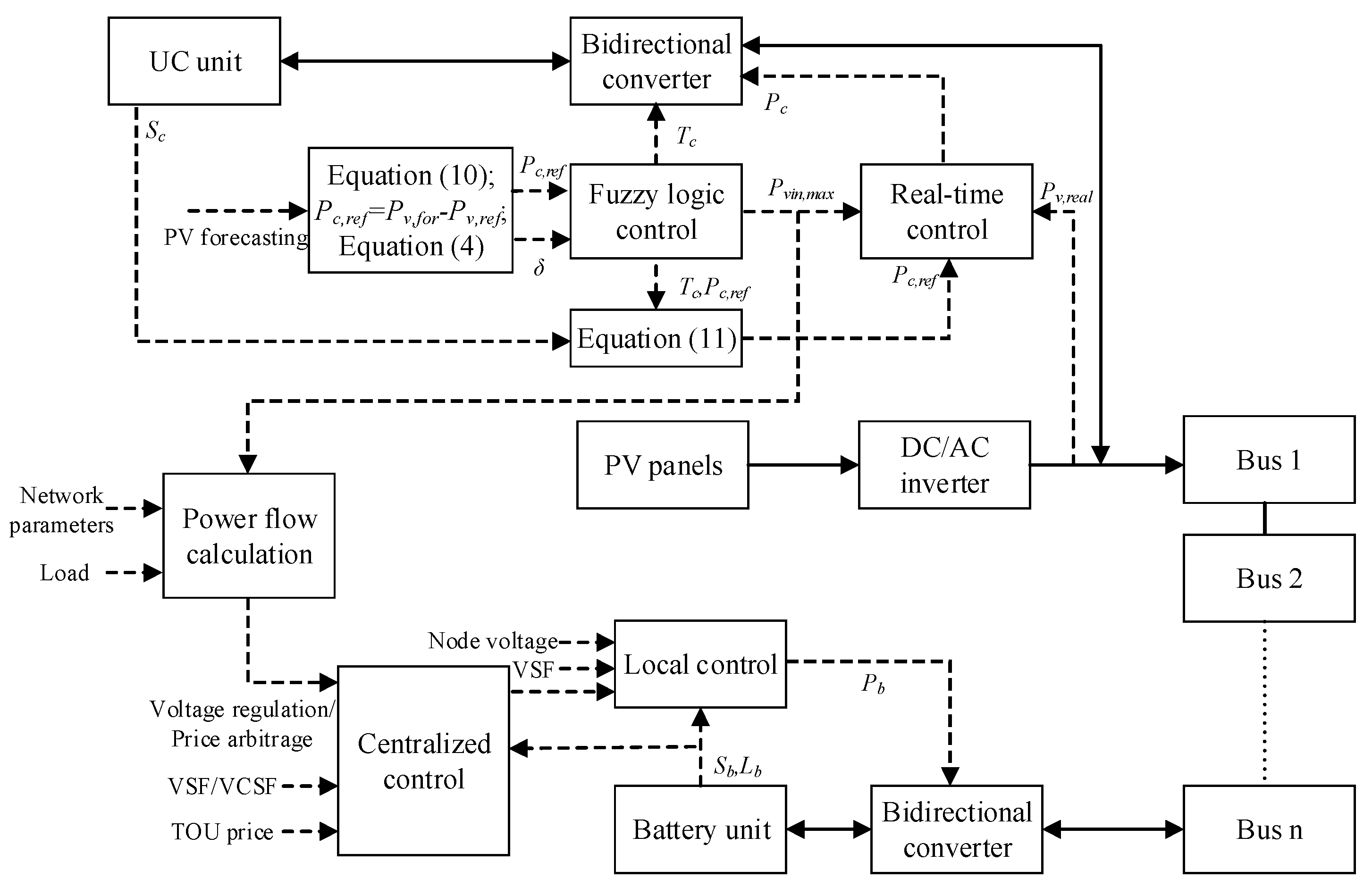
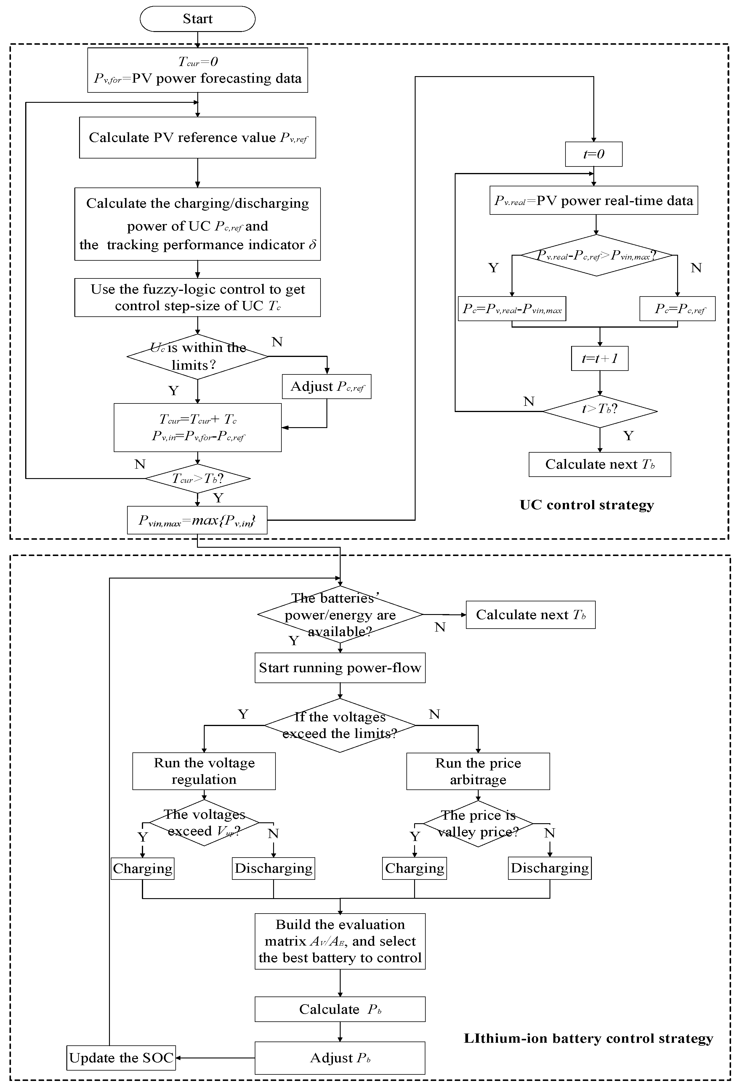
In this paper, a rule-based hierarchical operation strategy of HESS, including lithium-ion batteries and UCs, for PV power smoothing, voltage regulation, and price arbitrage is proposed. For some DNs with large R/X ratios, the regulation effects of active power are more significant. Therefore, the active power of HESS is mainly considered in the proposed strategy. Firstly, a fuzzy-logic based variable step-size control strategy for UC is proposed to smooth PV power fluctuation which improves the UC lifetime as well as the tracking performance. The impact of PV forecasting error is eliminated by adjusting UC power in real time. Secondly, in the coordinated control for lithium-ion battery, centralized control selects the optimal battery unit to perform voltage regulation or price arbitrage according to evaluation matrix considering battery performance indices such as State of Charge (SOC), charging/discharging power, remaining lifetime, voltage sensitivity factor (VSF), and voltage cost sensitivity factor (VCSF). The local control of the selected lithium-ion battery unit determines the charging/discharging power. A modified battery aging model with better accuracy is proposed. The main contributions of this paper are summarized as follows:
- (1)
A multi-objectives hierarchical operation strategy with consideration of PV power smoothing, voltage regulation, and price arbitrage is proposed, which can improve the effectiveness of utilizing HESS.
- (2)
A fuzzy-logic based variable step-size control strategy is designed for UC to prolong its lifetime and improve the tracking performance simultaneously.
- (3)
A more accurate aging model of lithium-ion battery considering the influences of solid electrolyte interphase (SEI) film, charging/discharging rate, temperature and other external factors is proposed. The coupling relationship between the lifetime and the effective capacity is also considered.
- (4)
Due to the consideration of lithium-ion battery lifetime and multi-objectives of HESS, the heavy workload of certain units is avoided and the lifetime equilibrium among different battery units is achieved.
The paper is organized as follows:
Section 2 describes the mathematical models of our problem.
Section 3 introduces the hierarchical optimal operation strategy for HESS. Finally, the results of case studies and conclusions are presented in
Section 4 and
Section 5, respectively.
4. Case Study
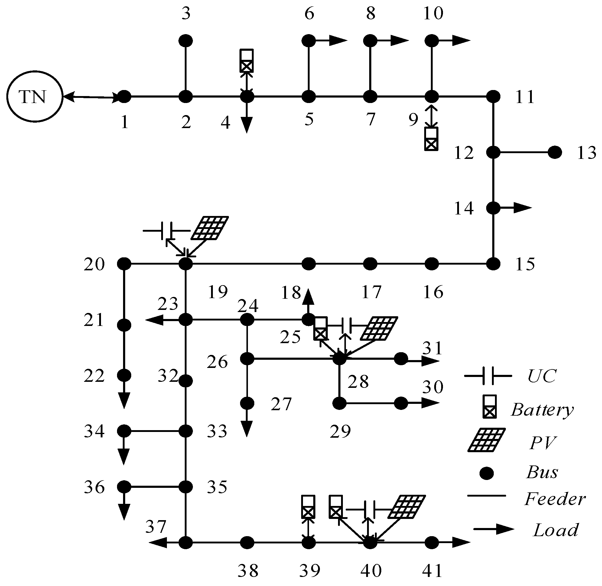
The proposed strategy is tested on a rural DN with 41 buses referring to [
21,
36,
37] which is shown in
Figure 5. The power base value is 10 MVA, the demand data are given in
Table 2 and the parameters of PV and HESS are given in
Table 3. According to GB/T 12325-2008 ‘power quality and supply voltage deviation’, 0.94–1.04 p.u. is selected as the limits of voltage deviations. The peak and valley prices are 0.5583 ¥/kWh (8:00–21:00) and 0.3583 ¥/kWh (21:00–8:00), respectively.
In this section, five cases are carried out to verify the effectiveness of the proposed control strategy. The length of the test period of Case 1 to Case 3 is 24 h, and the control step-size of lithium-ion battery is 15 min. The five cases are summarized as below:
- Case 1:
The control step-size of UCs is constant, e.g., 1 min, and the batteries are only used for voltage regulation.
- Case 2:
The control step-size of UCs is constant, e.g., 1 min, and the batteries are used for both voltage regulation and price arbitrage.
- Case 3:
The control step-size of UCs is adjusted by the fuzzy-logic control, and the operation strategy of batteries is identical with Case 2.
- Case 4:
The control strategy of HESS is identical with Case 3. The fault situation, i.e., breakdown of battery unit, is discussed to verify the robustness of the proposed control strategy.
- Case 5:
The influences of different battery control strategies on battery lifetime are compared in this case and the effects of the lifetime equilibrium among different battery units are shown with different initial lifetime states.
4.1. Case 1
In this case, the control step-size of UC is constant, e.g., 1 min, which means the charging/discharging power of the UC Pc updates every minute according to Pv and Pref. The batteries are only used for voltage regulation. That is, when all the node voltages are within the limits, the control of lithium-ion battery will not be triggered.
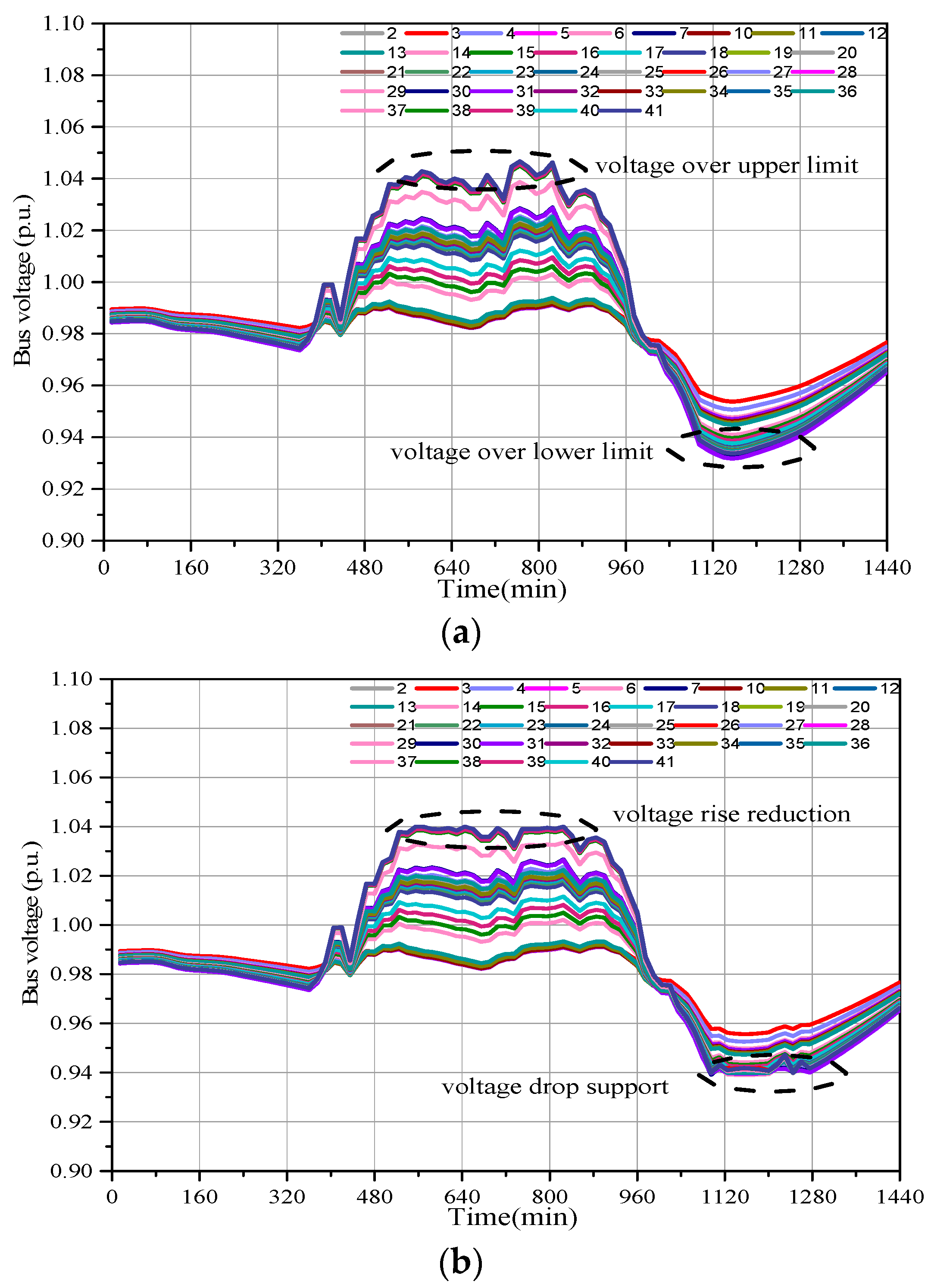
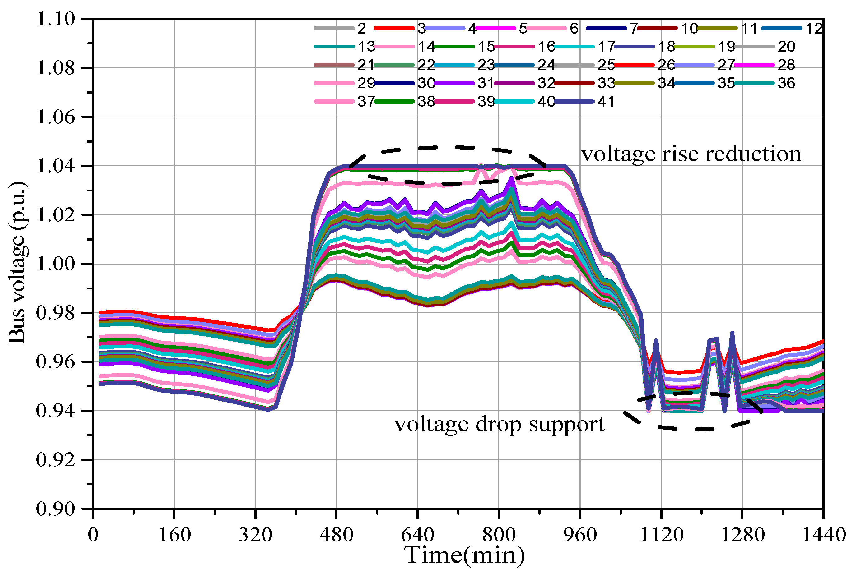
Figure 6 shows the curves of node voltages of different cases. In
Figure 6a, from 10:00 to 14:00, the PV power is much larger than the load because of the intense solar radiation which eventually leads to the node voltage violation. During 18:00–22:00, the PV power is zero, but the load is heavy, so the voltage violation occurs and there are 28 nodes’ voltages violating the lower limit with the peak load at 20:00. In
Figure 6b, the voltage issues are solved by the introducing of HESS.
4.2. Case 2
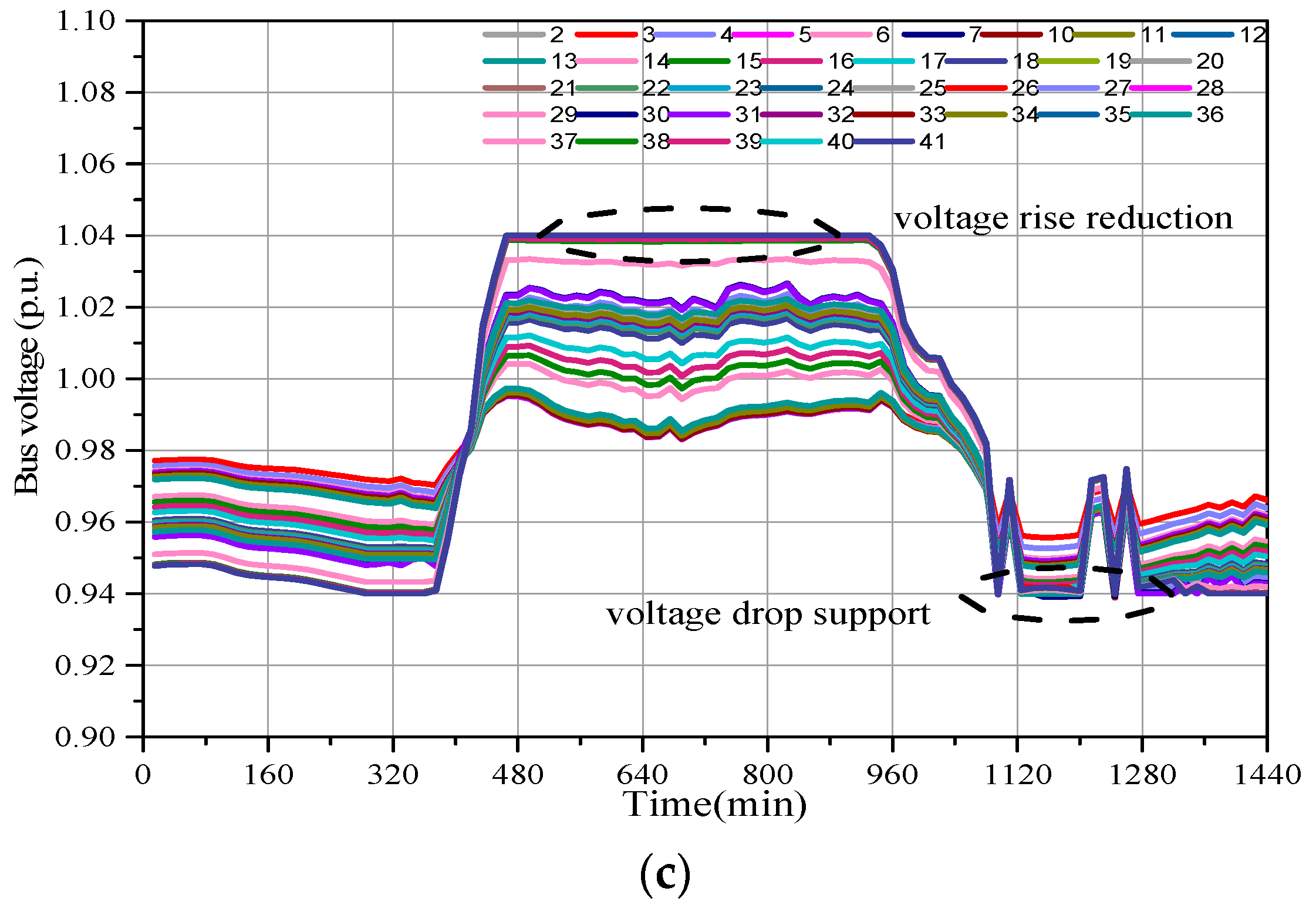
From
Figure 6c, to realize price arbitrage, the batteries are preferring to charge in the valley price period (21:00–8:00) and discharge in the peak price period (8:00–21:00) while keeping the voltage within the limits. The annual HESS profit is calculated and the economic comparison is shown in
Table 4.
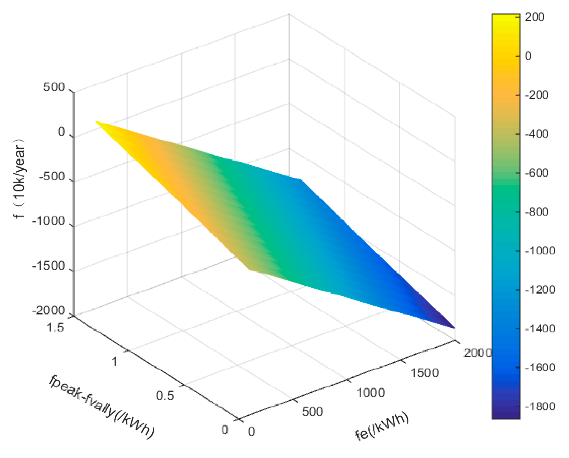
In the case without batteries, the punishment cost of voltage violation is high, even though there are no investments for batteries. The annual profit is still less than that in Case 1 and Case 2. Because of price arbitrage operations, the gains in Case 2 are significantly improved, and the annual profit is 128.047 k¥ more than that in Case 1. However, as shown in
Table 4, the current annual profits of three cases are all negative because the HESS cost is high and energy conversion efficiency is low and the difference between peak and valley price is not large enough compared with the developed countries, where the on-peak electric price can be 4 to 5 times higher than the off-peak price. The relationship between Case 2 annual profit and two influencing factors (unit capacity cost of battery
fe and the difference between peak and valley price
fpeak −
fvally) is shown in
Figure 7. With the development of technology and the improvement of relevant support policies, the economy of HESS will be further improved.
4.3. Case 3
In Case 3, the battery control part is identical with Case 2, so the results of voltage regulation and price arbitrage are not repeated here.
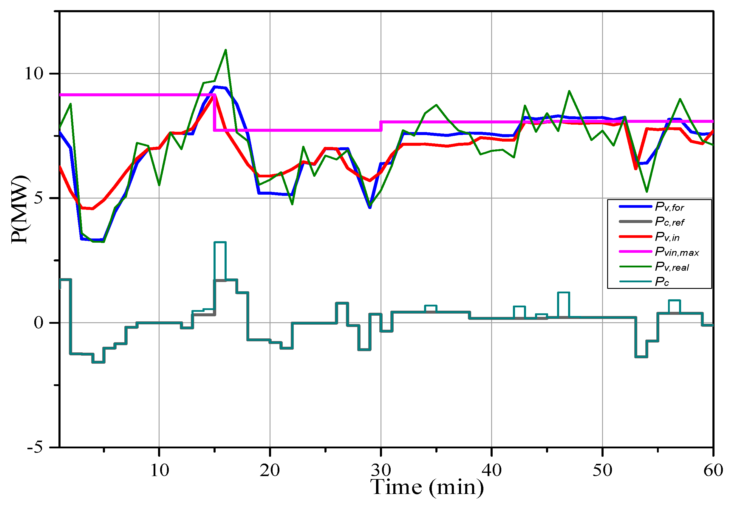
Figure 8 shows the results of PV power smoothing and real-time adjustment of UC during 11:00–12:00.
Pv,real and
Pv,for are the real-time and forecasting data of PV power, respectively.
Pc,real and
Pc,ref are the charging/discharging power of UC based on the actual and forecasting data of PV power, respectively. When |
Pc| is large, the control step-size is smaller, otherwise the control step-size is larger. This obeys the rules of the fuzzy-logic control, and the effects of UC variable step-size control strategy on its remaining life
Lc and tracking performance indicator
δ are shown in
Table 5. According to Equations (3) and (4), the more ∑|
PcTc| and
δ is close to zero, the better that the lifetime state and tracking performance of UC will be. From
Table 5, when the control step-size is 1 min, the tracking performance is the best, but the value of ∑|
PcTc| is about 1.5 times of variable step-size control. When the control step-size increases, both of ∑|
PcTc| and
δ are larger than variable step-size control. And the variable step-size control strategy has better performance both on the improvement of UC lifetime and tracking performance.
4.4. Case 4
In Case 4, the operation strategy of HESS is identical with the strategy in Case 3. To verify the robustness of the proposed control strategy, a fault situation is analyzed, i.e., a fault occurs and the battery unit installed on bus 4 does not response for one whole day. As shown in
Figure 9, although the curves of node voltages are different from the case with all the battery units in
Figure 6c, the voltage security is maintained with the proposed control strategy. However, because of the reduction of the total charging/discharging energy of batteries, the daily profit decreases comparing to Case 3 which is shown in
Table 6. In all, the available batteries are settled optimally to solve voltage violation problems in Case 4. Furthermore, in some serious faults, PV power curtailment or load shedding may be required to guarantee the voltage security when the capability of the available batteries is insufficient.
4.5. Case 5
In Case 5, the operation strategy of HESS is tested for a long period to show the lifetime equilibrium among different battery units.
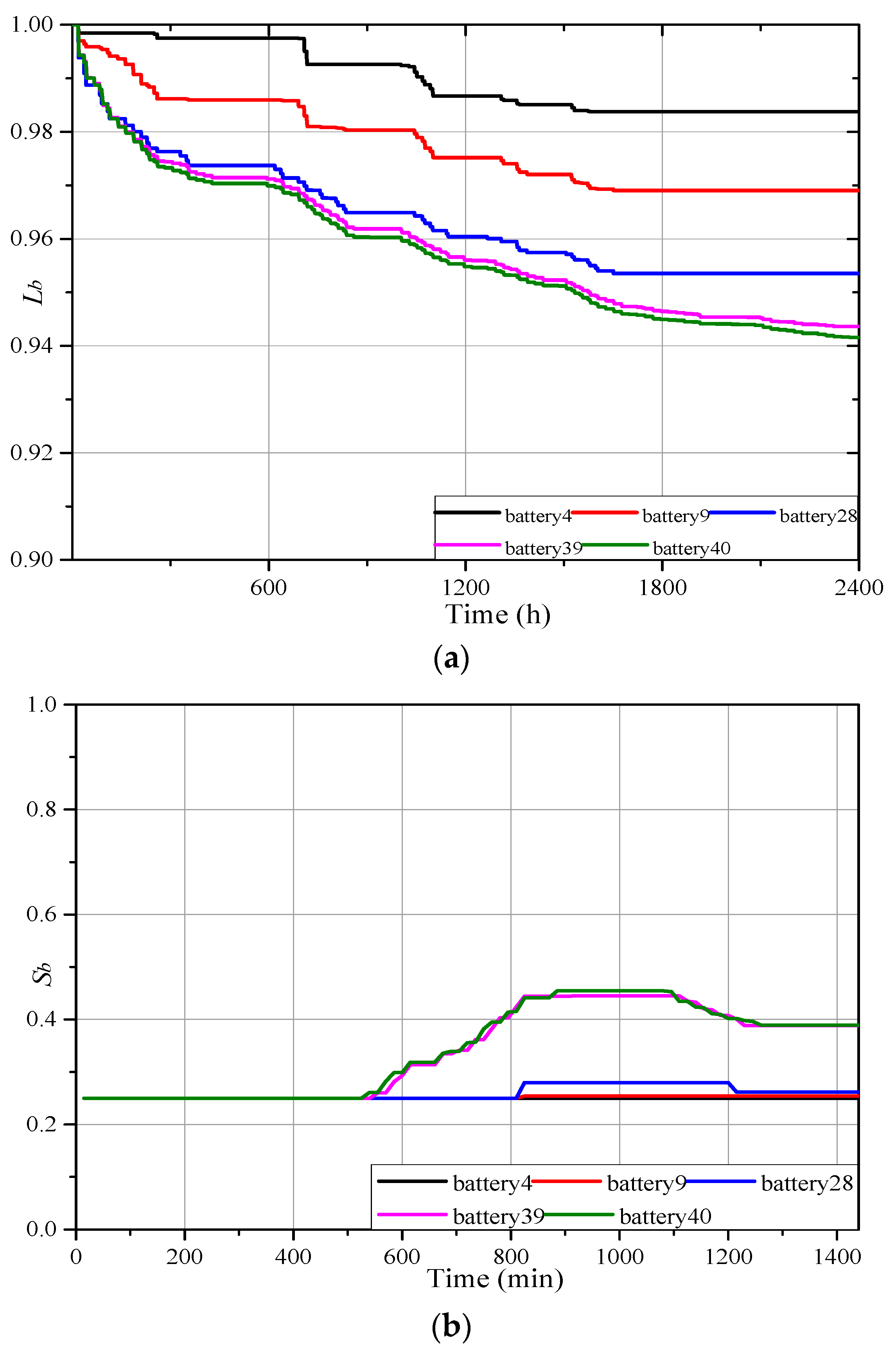
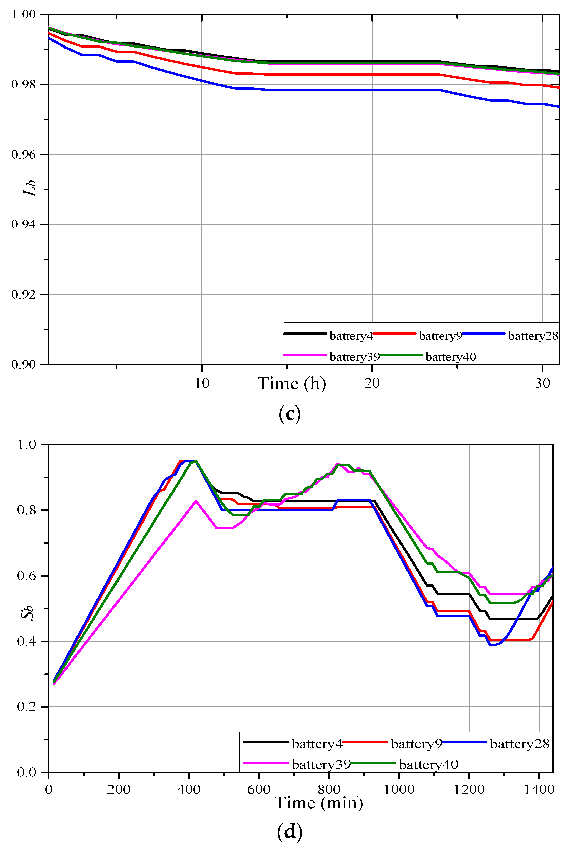
According to the characteristics of radial DNs, the voltage deviation of the terminal node is usually large. Therefore, in the process of voltage regulation, the batteries at the end of the line are used frequently which causes the unbalanced utilization rate. With the price arbitrage process, the batteries installed at the beginning of the line are also utilized fully because of the small VSFs. Therefore, the utilization ratios among different battery units are balanced with the proposed operation strategy which combines voltage regulation and price arbitrage. This is beneficial to the average battery lifetime. In
Figure 10a, the batteries only operate voltage regulation and the differences among their utilization ratios are large. However, in
Figure 10c, where the proposed operation strategy is adopted, when the remaining lifetime of battery installed at node 4 is the same as that in
Figure 10a, the lifetime differences among different battery units are smaller.
Figure 10b,d show the curves of batteries SOC during one day when they are used for voltage regulation and both voltage regulation and price arbitrage, respectively. It is shown that the batteries at the beginning of the line (battery 4, battery 9) are almost not used in
Figure 10b, and it eventually leads to the unbalanced utilization rates between different battery units in
Figure 10a.
In addition, the battery lifetime is considered in the lithium-ion battery control strategy when selecting the optimal battery units. Based on this, the working conditions of different battery units are optimized according to different lifetime states. The proposed operation strategy is carried out with identical or different initial life states for one year.
Table 7 shows the results and
Eb is the charging/discharging energy of battery. Compared to cases with the same initial lifetime states, when the initial lifetime states are different, the charging/discharging energies of batteries installed on bus 4, 9 and 28 increases significantly, since for those batteries their initial lifetimes are longer than those installed on bus 39 and 40. Similarly, the utilization of the batteries installed on bus 39 and 40, whose initial lifetimes are shorter, will decrease accordingly. As a summary, the utilization ratios of the batteries with short initial lifetime will decrease, and the utilization ratio of the batteries with long initial lifetime will increase to achieve the equilibrium with the proposed operation strategy. Thus, it would benefit the achievement of lifetime equilibrium and the whole system operation.


