Article

Obstacle Avoidance Path Planning Design for Autonomous Driving Vehicles Based on an Improved Artificial Potential Field Algorithm

1
School of Transportation and Vehicle Engineering, Shandong University of Technology, Zibo 255000, China
2
State Key Laboratory of Automotive Safety and Energy, Tsinghua University, Haidian District, Beijing 100084, China
*
Authors to whom correspondence should be addressed.
Submission received: 29 April 2019 / Revised: 28 May 2019 / Accepted: 17 June 2019 / Published: 19 June 2019

Abstract

:
Obstacle avoidance systems for autonomous driving vehicles have significant effects on driving safety. The performance of an obstacle avoidance system is affected by the obstacle avoidance path planning approach. To design an obstacle avoidance path planning method, firstly, by analyzing the obstacle avoidance behavior of a human driver, a safety model of obstacle avoidance is constructed. Then, based on the safety model, the artificial potential field method is improved and the repulsive field range of obstacles are rebuilt. Finally, based on the improved artificial potential field, a collision-free path for autonomous driving vehicles is generated. To verify the performance of the proposed algorithm, co-simulation and real vehicle tests are carried out. Results show that the generated path satisfies the constraints of roads, dynamics, and kinematics. The real time performance, effectiveness, and feasibility of the proposed path planning approach for obstacle avoidance scenarios are also verified.

1. Introduction

1.1. Background and Previous Works

Studies on autonomous driving vehicles have become a hot topic in both industry and academia in recent years [1,2]. Autonomous driving systems could replace human drivers and control the motion automatically based on road conditions and vehicular states [3]. Therefore, autonomous driving vehicles are considered as solutions to improve road efficiency and driving safety. As a result of the development of sensor technology, electronic control technology, and artificial intelligence technology, autonomous driving vehicles are expected to be more intelligent and more humanized. Accordingly, the design of decision-making and planning systems for autonomous driving vehicles that could handle dynamic traffic scenarios is a significant research subject [4]. Completing obstacle avoidance operation based on mixed perception information is one of the core functions of decision making and planning modules. The key technologies of obstacle avoidance include decision making, path planning, and path tracking [5]. Therefore, research on obstacle avoidance path planning for autonomous driving vehicles has important practical significance and application prospects.
Path planning modules could generate a reference path, which could avoid obstacles and satisfy the demand of road safety and vehicle dynamics constraints [6,7]. Research on obstacle avoidance path planning algorithms in dynamic environments for autonomous driving vehicles is always the focus and difficulty. Numerous works on autonomous driving vehicle obstacle avoidance path planning have been done. A variety of algorithms have been applied to related research. At present, the primary methods include the artificial potential field method (APF), genetic algorithm, rapidly-exploring random tree method (RRT), fuzzy logic algorithm, neural network method, rolling window method, and the combination of above methods [5,7]. In addition, more sophisticated methods are applied in autonomous navigation of mobile robots, such as synthetic vision [8]. Unlike mobile robots, obstacle avoidance path planning algorithms for autonomous driving vehicles should meet the requirements of path safety, computation speed, and system robustness simultaneously. The artificial potential field algorithm structure is simple, meaning it could satisfy the requirement of real time control. Accordingly, the algorithm has significant advantages to deal with path planning for real time obstacle avoidance [9]. Because of these advantages, the artificial potential field is widely used in practical projects, but its performance needs to be improved.
Xiu proposed a path planning method based on improved artificial potential field [10] by introducing adjustment factors and rebuilding the attraction of the target point, meaning the local minimum problem of the traditional artificial potential field was improved. However, the generated path was not optimal. In order to improve the safety of the obstacle avoidance path, Wang proposed a new virtual force field action scope of obstacles, which considered the operating condition of the front vehicle [11]. Then, an improved overtaking path planning model was established. The presented obstacle potential field ignored some dynamic parameters. For the purpose of enhancing the safety of obstacle avoidance planning, Luo designed a trajectory planning method based on the quantic polynomial trajectory function [12]. The proposed method could update the reference trajectory during lane change. Ji proposed a 3D virtual dangerous potential field model to quantify driving risk [13,14], based on which the path planning and path tracking of autonomous vehicles were completed. Meanwhile, complex dangerous potential models lead to large computation. Wang proposed a path planning method based on model predictive control algorithm [15]. By combining artificial potential field and crash severity factors, a cost function was constructed. The collision damage was minimized by solving the proposed cost function. Chen presented an obstacle avoidance method for low speed autonomous vehicles based on the polar algorithm [16]. The algorithm has strong adaptability under complex scenarios.
In addition to improving the performance of obstacle avoidance path planning algorithms, scholars have also devoted themselves to quantifying the risk change in the obstacle avoidance process [17,18]. Wang proposed a unified driving safety field model based on field theory [19]. The proposed driving safety field model considered the risk factors of vehicles and road environments. The obstacle avoidance path can be generated based on the proposed model. The application of driving safety field theory needs further verification and research. Wang fused vehicle parameters and driver intent to assess driving risk rapidly [20], and according to the result of risk assessment, a smooth safe collision avoidance trajectory was planned based on an improved rapidly-exploring random tree algorithm.
Most current studies based on the artificial potential field have not considered the impacts of different driving behavior and obstacle characteristics on the path planning result. Obstacle potential field is simplified as rectangles or circles. The constraints of road boundaries, vehicle kinematics, and dynamics on obstacle avoidance paths are neglected. Dynamic obstacle avoidance path planning should take the motion characteristics and hazard index of obstacles into consideration [11,21]. Furthermore, most existing risk assessment models are too complex to be applied in the obstacle avoidance system. Therefore, how to quantify the risk changes in the process of vehicle obstacle avoidance and generate a reasonable obstacle avoidance path are the keys to the current research of automatic driving vehicle obstacle avoidance. Given the above analysis, based on the basic theory of artificial potential field method, an obstacle avoidance path planning method is designed. The main contributions of this paper are summarized as follows: (i) By analyzing the characteristics of human drivers, a safety model of obstacle avoidance is proposed. (ii) Based on the safety model, an obstacle avoidance path planning approach is proposed, which could generate a collision free path for autonomous driving vehicles in dynamic environments. (iii) Extensive simulations and real vehicle tests are carried out, and the performance of the proposed approach is assessed.

1.2. The Organizztions

The rest of this paper is organized as follows. By analyzing the law of human driver obstacle avoidance maneuvers, an improved driving risky assessment model is constructed in Section 2. Then, based on the risk model, an improved artificial potential field model of road environments and obstacles is established in Section 3. Finally, an obstacle avoidance path with multiple constraints is obtained. Simulink/CarSim co-simulations and real vehicle experiments are carried out to validate the proposed path planning algorithm in Section 4 and Section 5.

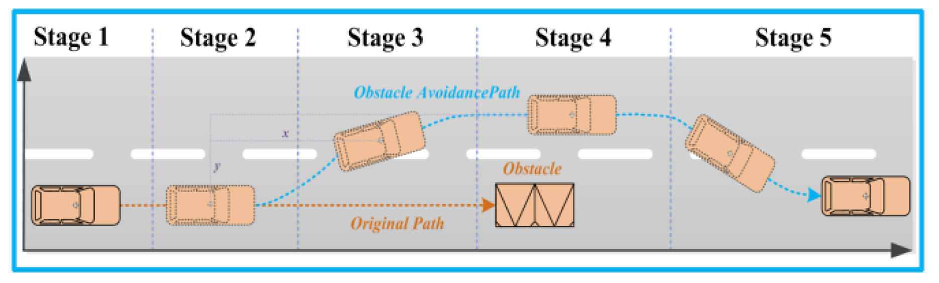
2. Description of Obstacle Avoidance Maneuver

2.1. Analysis of Obstacle Avoidance Process

Obstacle avoidance maneuvers of autonomous driving vehicles consists of two parts: vehicle collision risk assessment and obstacle avoidance path planning. In order to ensure the safety of the generated path, the path planning process of human drivers is analyzed in this chapter. Obstacle avoidance operations performed by human drivers are based on the understanding of dynamic traffic scenarios, and then obstacle avoidance decision-making and path planning are completed. However, there are many obstacle avoidance judgment criteria for drivers. The main basis of risk assessment is different for different drivers, even in same scene. As shown in Figure 1, the whole behavior of obstacle avoidance could be divided into five sub-behaviors.
Stage 1: Scene recognition for obstacle avoidance: identify whether current scenario meets the criteria of obstacle avoidance, such as obstacles on the driving route, ego vehicle speed is greater than the obstacle, and there is enough space to complete an obstacle maneuver.
Stage 2: Computation and path planning: a collision free path is planned based on environmental information.
Stage 3: Changing lane to bypass obstacles: in order to track the generated obstacle avoidance path, a lane changing maneuver is carried out.
Stage 4: Overtaking: the obstacle is overtaken after the lane change.
Stage 5: Back to original lane: when the obstacle is left behind over a certain distance, ego vehicle goes back to the original lane.

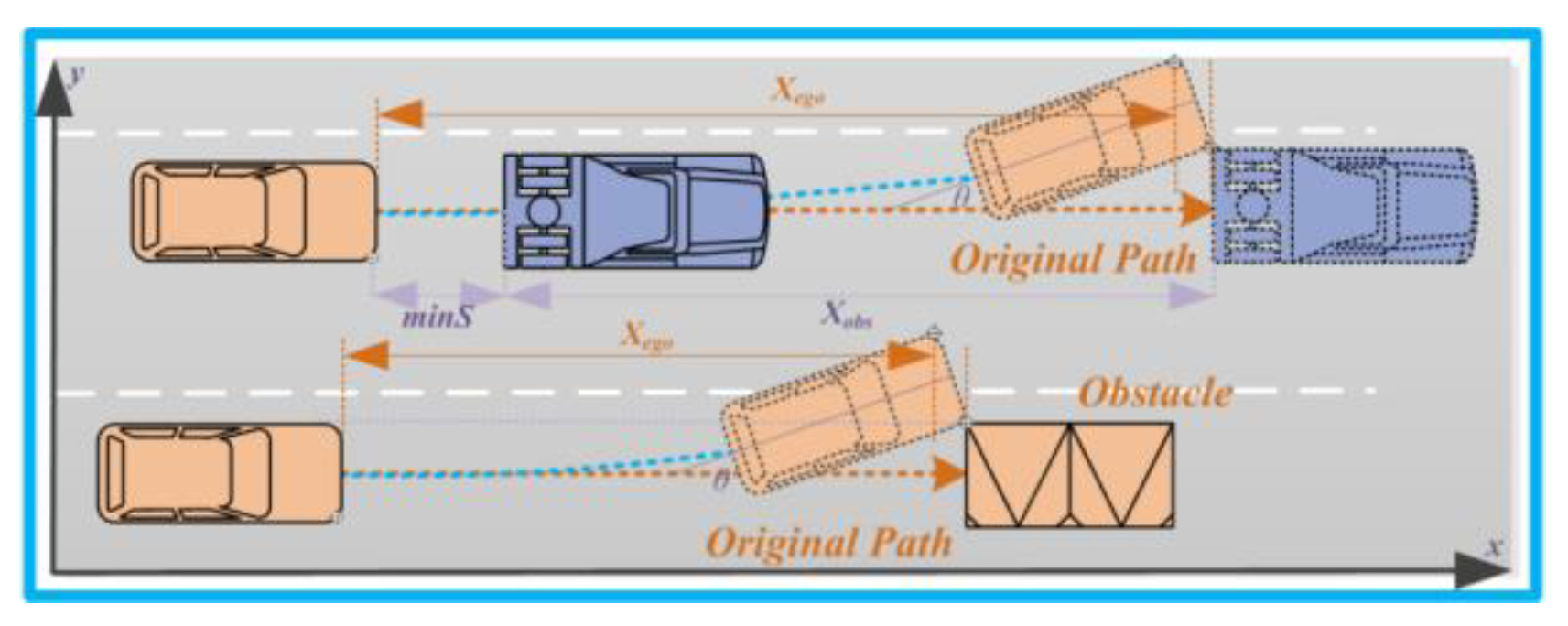
2.2. Safety Model of Obstacle Avoidance

According to the research of the National Highway Traffic Safety Administration (NHTSA), nearly 30% of traffic accidents happened during lane changes [22]. In order to reduce the loss and injury caused by accidents, scholars proposed a lane change hazard perception model based on the behavior of drivers [13]. Results show that the speed, movement state, and the properties of obstacles determine the severity of traffic accidents [23]. Other relevant studies also confirmed this point [19,24]. Therefore, in order to ensure safety, a time to predict risk advance of 0.3–1 s would be in accordance with the psychological and operation characteristics of drivers [24]. Based on the abovementioned facts, a simplified obstacle avoidance model is constructed by combining the driving risk model and driver behavior characteristics. By analyzing the operation characteristics of human drivers, it can be found that the parameters of obstacles have great influence on Stage 1. For example, when the mass and volume of obstacles ahead are large, drivers tend to perform obstacle avoidance maneuvers earlier. In Stage 3 and Stage 4, drivers tend to increase steering angle and reserve more lateral distance to bypass an obstacle when the obstacle has a larger volume or trend of lateral movement. During the actual driving, the most difficult issue is to deal with moving obstacles, such as obstacle vehicles, pedestrians, and other traffic participants. Obstacle avoidance strategies aimed at static and moving obstacles are different in realistic scenarios.
It is known from analysis that for autonomous driving vehicles, the calculation results of stage 2 would affect the follow-up operation of obstacle avoidance directly. Further operations are more dependent on the control precision of actuators. In stage 3, the probability of collision is greater than other stages. If no collision occurs in this stage, it means the ego vehicle avoids the obstacle successfully. Therefore, the safety model of obstacle avoidance needs to be built to ensure the safety of the obstacle avoidance path.
As shown in Figure 2, the condition for collision avoidance between vehicle and obstacle is as follows:
X e g o + w s i n θ < X o b s + S
where X e g o is the longitudinal displacement of the ego vehicle during the time of obstacle avoidance operation; X o b s is the longitudinal displacement of the obstacle vehicle during the time of ego vehicle obstacle avoidance operation; S is the initial distance between the ego vehicle and the obstacle vehicle ;   w is the width of the ego vehicle; θ is the angle between the x-axis of the vehicle coordinate and the lane. The value of θ is related to the lateral velocity.
The longitudinal displacement of the ego vehicle during the time of obstacle avoidance operation could also be expressed with the equation:
X e g o = 0 t c X e g o ˙ d t
The longitudinal displacement of the obstacle vehicle during the time of the ego vehicle obstacle avoidance operation could also be expressed with the equation:
X o b s = 0 t c X o b s ˙ d t
In order to ensure no collision occurs in the lane change progress, according to Equation (1), it can be deduced that the initial distance S should satisfy:
S = X e g o + w s i n θ X o b s > 0
Combining the above equations and the kinematic relationship of vehicles in the obstacle avoidance process, the minimum longitudinal safety distance required to complete obstacle avoidance without collision could be expressed by the equation:
m i n S = { ( X e g o ˙ X o b s ˙ ) t c + 0 t c ( X e g o ¨ ( t ) X o b s ¨ ( t ) ) d t + w s i n θ , 0 }
In real traffic scenarios, the relative velocity of overtaking is relatively low, resulting in larger errors in the calculation results of Equation (5). Beyond this, to ensure driving safety, Equation (5) is improved with the consideration of time headway and driver behavior characteristics.
m i n D = m i n S + c ( X o b s ˙ X o b s ˙ ) + d 0 + σ ( X o b s ˙ X o b s ˙ )
where c represents headway, d 0 is safety breaking distance, σ is the risk factor of the obstacle, which can be expressed as:
σ = G 1 m o b s w o b s G 2 S e x p G 3 m a x { ( X e g o ˙ X o b s ˙ ) , 0 }
where m o b s and w o b s are the mass and width of the obstacle, respectively. G 1 , G 2 , and G 3 are adjustment coefficients.
In general, the principle of human driver obstacle avoidance is similar to that of the artificial potential field. The basic idea is providing a collision-free path and setting apart an appropriate safety margin based on the types and the movement state of obstacles. The artificial potential field is ideal for describing the scenarios of obstacle avoidance. Therefore, how to improve the artificial potential field and apply it to obstacle avoidance scenarios is also an urgent problem to be solved.

3. Obstacle Avoidance Path Planning Based on Artificial Potential Field Method

3.1. Design of Artificial Potential Field

The artificial field potential approach was proposed by Khatib in 1986 [25,26]. Its basic principle is to describe realistic scenes by establishing an artificial virtual potential field. The vehicle tracks the path of resultant force decided by repulsion and attraction generated by the obstacle and target point. Due to the limitations of the classical artificial potential field algorithm, it could not be directly applied to obstacle avoidance path planning for autonomous driving vehicles [27]. Therefore, by improving the obstacle repulsive field function, an improved artificial potential field approach is proposed.
Assuming the position of ego vehicle is
X e g o p = ( x e g o , y e g o )
The position of target point is
X t g t p = ( x t g t , y t g t )
The position of obstacle is
X o b s p = ( x o b s , y o b s )
In the artificial potential field, the target point generates gravity. The gravitational field of the target point can be expressed with the equation:
U a t t = 1 2 k a t t ( X e g o p X t g t p ) 2
where k a t t is the coefficient of the gravitational potential field.
The ego vehicle moves towards the target point under the gravity generated by the target point. The value of gravitation decreases with the distance. Therefore, the gravitational force on the ego vehicle can be expressed as the negative gradient equation of the target point potential field.
F a t t = ( U a t t ) = k a t t a att
In the artificial potential field, obstacles generate repulsive fields. The gravitational field of an obstacle can be expressed with the equation:
U r e p = { 1 2 k r e p ( 1 ρ 0 1 ρ o b s ) 2 , ρ o b s > ρ 0 0   , ρ o b s ρ 0
where k r e p is the coefficient of the repulsive potential field; ρ o b s is the radius of the obstacle repulsive potential field; ρ 0 is the distance between the ego vehicle and the obstacle. The repulsive force on the ego vehicle can be expressed as:
F r e p = { k r e p ( 1 ρ 0 1 ρ o b s ) ( 1 ρ 0 ) 2 a r e p , ρ o b s > ρ 0 0   , ρ o b s ρ 0
In reality, the regular shape of the vehicle can be simplified as a cuboid on the road plane. The longitudinal velocity is much greater than lateral velocity in normal driving conditions. The smoothness of the obstacle avoidance path should also be considered. Therefore, on the basis of these, the potential field of obstacles is improved to ellipse.
x o b s 2 A 2 + y o b s 2 B 2 = 1
The parameters of the obstacle’s potential field are further optimized with the combination of safety models constructed in Section 2.
A = m i n D
B = δ σ · w o b s 2
where δ is the adjustment coefficient of the repulsive potential field, which is used to adjust the range of the potential field; w o b s is the width of obstacle.
The repulsive force can be expressed as:
F r e p = { k r e p ( 1 ρ 0 1 ρ o b s ) ( 1 ρ 0 ) 2 a r e p ,   X e g o p x o b s 2 A 2 + y o b s 2 B 2 = 1 0   , X e g o p x o b s 2 A 2 + y o b s 2 B 2 = 1
In the process of obstacle avoidance operation, repulsion generated by the obstacle and gravitation generated by the target point both act on the ego vehicle; specifically, at the time when the ego vehicle, obstacle, and target point are in the same line. The resultant force acting on the ego vehicle could be zero; the ego vehicle might stop, falling into a local minimum and causing target point to be unreachable. To solve this problem, a virtual target point is used in this paper. The first virtual target point is set in the target lane and the second virtual target point is set outside the range of the obstacle potential field in the original lane. The gravitation generated by the virtual target point could lead the ego vehicle, leaving the local minimum point [28].

3.2. Constraint Analysis for Obstacle Avoidance Path
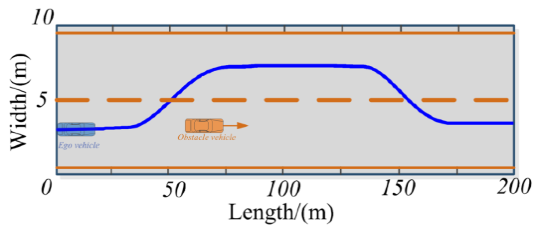
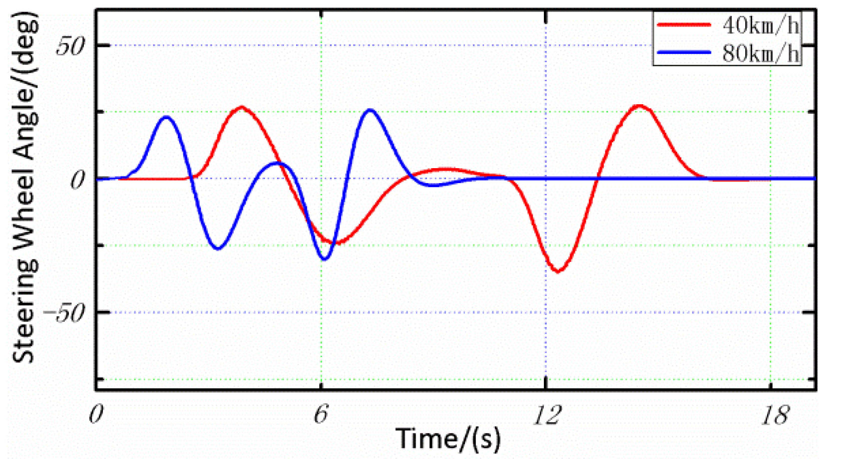
In addition to avoiding obstacles safely, the motion of vehicle should also satisfy the constraints of vehicle kinematics, dynamics, and roads. In structured roads, it is safest to drive in the middle of lane if no obstacle is detected. Frequent lane changes should be avoided, unless they are unavoidable. In order to avoid undesirable lane crossing, lane boundaries are proposed. Artificial potential fields are defined for lane lines:
U r o a d = { k r o a d e x p ( w l a n e 2 l e g o l ) , l e g o l ( w e g o 2 , w l a n e 2 ) 0 ,     l e g o l , l e g o l ( w e g o 2 , w l a n e 2 ) k r o a d e x p ( w l a n e 2 l e g o r ) , l e g o r ( w e g o 2 , w l a n e 2 )
where k r o a d is the coefficient of the potential field; l e g o r is the distance between the ego vehicle and the right lane line, and l e g o l is the distance between the ego vehicle and the left lane line; w l a n e and w e g o represent the width of the lane and vehicle, respectively. The proposed lane boundaries could keep the vehicle in the middle of the lane, even after changing into a new lane.
In addition to boundaries of the road and obstacles, the path generated by the improved artificial potential field function should also take the dynamic constraints of the vehicle into consideration. During the obstacle avoidance process, the ego vehicle changes lane twice. An unduly large steering angle will affect the dynamic steering stability of the vehicle. Therefore, in order to ensure the driving safety, the steering angle and speed should meet certain conditions for stability to ensure steering performance and steering stability. Taking into consideration tire stiffness, the lateral acceleration of the vehicle should not exceed 0.4 g [29]. To prevent sideslip of the vehicle, the lateral acceleration of vehicle should not exceed 0.75 μg [30,31]. To satisfy the stability of obstacle avoidance, vehicle lateral acceleration constraint could be expressed as:
m i n a y = m i n { 0.4 g , 0.75 μ g }
Based on the two-degree-of-freedom vehicle model [28], the equation between lateral acceleration and front wheel angle is derived:
| β l i m | = | m i n a y ( 1 + K v x 2 ) l v x 2 |
where K is the stability factor of the vehicle, β is the front wheel angle, l is the wheelbase of the vehicle, and v x is the longitudinal velocity of vehicle. According to the above analysis, to ensure steering stability of the vehicle, the value of the front wheel angle should satisfy:
| β r e a l | < | β l i m |

4. Simulation Test

In order to test the feasibility of the generated path, the proposed algorithm is co-simulated under CarSim/MATLAB software environment. Figure 3 shows the implementation of co-simulation. A typical obstacle avoidance scenario is constructed. In the constructed scenario, dynamic obstacles are set up and environmental information is known. The type, velocity, and measurement of obstacles are known. Obstacle parameters are used as inputs for the proposed model. Then, based on the model, a reference path is generated. Finally, the reference path is converted to vehicle position information.
In the constructed scenario, the obstacle vehicle is moving on a straight road with a constant speed of 15 km/h. The ego vehicle is moving at 40/80 km/h in the same lane. In order to avoid collision, an overtaking path is generated by the path planning module based on the information of the obstacle vehicle. After bypassing the obstacle vehicle, the ego vehicle changes back to the original lane. The generated path and constructed scenario are shown in Figure 4.
In the simulation, a virtual vehicle model is built in CarSim; vehicle model parameters are shown in Table 1. The virtual driver model is used to track the generated path. By analyzing vehicle real-time running data, the feasibility and effectiveness of the algorithm are verified.
Figure 5 shows the curves of the steering wheel angle. The curves of the steering wheel angle are smooth and continuous without oscillation or mutation. This indicates that the generated path is feasible and it conforms to the operating characteristics of a human driver.
Figure 6 shows the curves of the front wheel angle. As shown in the figure, the value of the front wheel angle is between ±2 degrees. The value meets the stated constraints. The curves of the front wheel angle are smooth and continuous without oscillation and mutation.
Figure 7 shows the curves of lateral acceleration. As shown in the figure, the lateral acceleration is greater when the vehicle performs an obstacle avoidance maneuver at a speed of 80 km/h; the maximum value of lateral acceleration at 80 km/h is 0.35 m/s2. The maximum value of lateral acceleration is less than 3.92 m/s2 (0.4 times gravity acceleration). Relatively low lateral acceleration constrains the tires within the linear region and ensures the stability and comfort of the vehicle.
Figure 8 and Figure 9 show the curves of yaw and yaw rate of the vehicle, respectively. As shown in the figure, when the velocity of the vehicle is 40 km/h or 80 km/h, the yaw rate of the vehicle is always in the range of ±9.5 deg/s, and the yaw of the vehicle is in the range of ±9 deg. This means the vehicle could keep its stability at both high speed and low speed. The probability of side slip and tail flick is very small.
Figure 10 shows the curves of roll angle. Roll angle is an important parameter to characterize the probability of vehicle rollover. As shown in the figure, the roll angle is greater while the vehicle performs obstacle avoidance maneuvers at a speed of 80 km/h. The roll angle of 80 km/h is always in the range of ±0.95 deg during the experiment. This indicates that the possibility of vehicle rollover is extremely low.
Simulation results show that the planned path is collision free, and the driver could track the generated reference path at 40 km/h and 80 km/h accurately. Further analysis shows that the generated path could ensure handling stability and riding comfort, even when the vehicle is tracking at high speed. This demonstrates the satisfactory feasibility and real time performance of the proposed path plan approach.

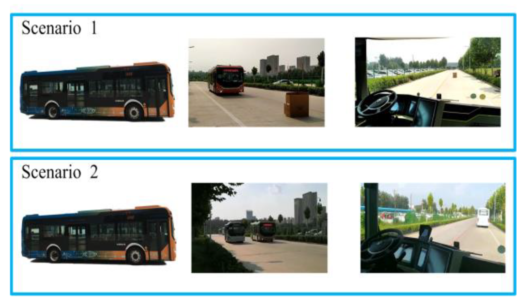
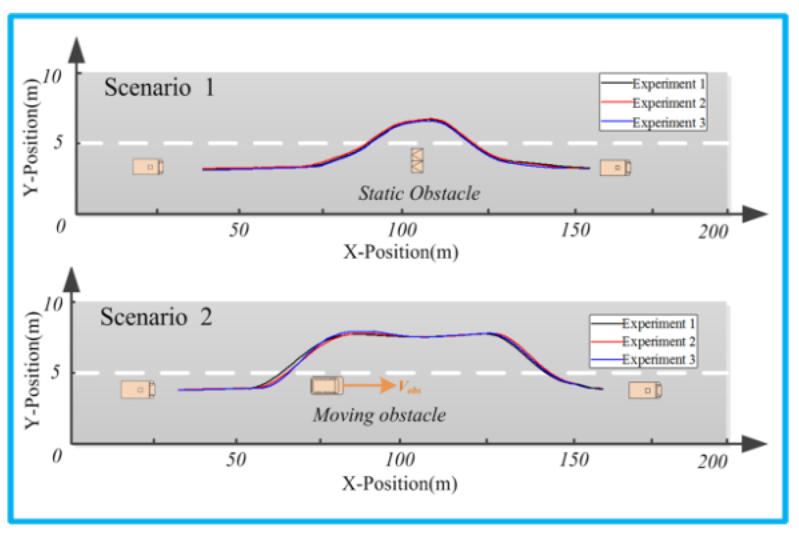
5. Real Vehicle Test

In order to test the performance of the proposed path planning method, the algorithm is implemented and tested on an experimental vehicle. The experimental vehicle is equipped with Differential Global Positioning System (DGPS) and Inertial Measurement Unit (IMU) to achieve self-localization and navigation. The position accuracy error is less than 2 centimeters. Lidar (VLP-16), Electronic Scanning Radar (ESR), and a Mobileye Camera are equipped to acquire real time environment information and detect collisions. To manipulate the vehicle, an automatic driving system is equipped. The system controls the bottom actuators to complete steering, breaking, and acceleration of the vehicle automatically. All actuators are controlled by the MicroAutobox through CAN Bus. The experimental vehicle configuration is shown in Figure 11.
In the experiment, a driving scenario of a straight road with two lanes is constructed. The width of the test road is 10 m. The length of the test road exceeds 500 m. Positioning devices are used to locate the current position and generate the reference path. Obstacles are set on the driving path. The experimental scenarios are shown in Figure 12. To compare the performance of the proposed approach, the performance of the artificial potential field approach is given in the same experimental conditions.
In scenario 1, a static obstacle is set. In scenario 2, the obstacle vehicle is moving at 10 kilometers per hour. The initial velocity of the ego vehicle is 20 kilometers per hour. In order to ensure the validity and reliability, a series of repeated experiments are carried out. In the experiment, the obstacle avoidance maneuver is divided into vehicle collision risk assessment and obstacle avoidance path generation. Collision risk assessment is completed by processing environmental data from sensors and calculating the current risk index. Based on the calculations, the original path is modified and a new collision free path is generated. The proposed path planning algorithm is tested on the experimental vehicle. Based on the proposed obstacle avoidance method, the experimental vehicle can avoid the pre-set obstacles automatically. The track data is recorded. Then, the actual path is plotted in GPS coordinates. The experiments results are shown in Figure 13 and Figure 14. Figure 14 shows the results of contrast tests.
Experimental results show that the proposed algorithm could generate collision free paths for autonomous driving vehicle in both scenarios. In scenario 1, the static obstacle on the original path is detected. Based on the calculation result, a new path is generated. In order to track the reference path, a lane changing maneuver is carried out. The vehicle bypasses the repulsive field range of the obstacle. Then, in the combined effect of attraction and repulsion, the experimental vehicle returns to the original lane. In scenario 2, the obstacle vehicle is driving at a relatively low speed. The experimental vehicle detects the moving obstacle vehicle and obtains detailed information for it. Based on the data of the obstacle vehicle, an overtaking path is generated. Compared with scenario 1, the repulsive field range of the obstacle vehicle is wider. The main reason for this lies in that the moving obstacle has different types and motion states. The desired path generated from the obstacle potential field function could enhance greater safety margins to avoid collision. The results of real vehicle experiments further evidenced the effectiveness and practicability of the proposed path planning approach. The generated paths are collision free and conform to the driving habits of human drivers. The real-time performance and stability of the algorithm are also verified by repeated tests.
Contrast tests results are shown in Figure 14; by adjusting the relevant parameters, the experimental vehicle could also complete obstacle avoidance. Nevertheless, the generated path is inferior in availability. The smoothness of the generated path is relatively low, especially in the initial stage of the lane change. In order to ensure the tracking accuracy and the safety of the test, contrast tests are implemented at lower speeds. Furthermore, the generated paths have not considered the motion characteristics and hazard index of the obstacles, the safety margin is not large enough, and the safety of the ego vehicle is not guaranteed. Therefore, the proposed path planning approach leads to better performance than contrasting ones.

6. Conclusions

In this paper, an obstacle avoidance path planning method for autonomous driving vehicles is proposed. By analyzing the path planning mechanisms of human drivers, a safety model is presented. The proposed model has considered multiple traffic factors. It is able to quantify the potential risks of obstacles effectively. Then, the potential field function of repulsive force is improved based on the proposed safety model. Furthermore, according to the improved artificial potential field, a collision free path is generated. The generated path is available, which could satisfy the constraints of roads, dynamics, and kinematics. Simulation and experimental results demonstrated the real time performance and the feasibility of the proposed path planning approach. Real vehicle experimental results demonstrate the effectiveness of the proposed approach in terms of obstacle avoidance for both static and moving obstacles. Furthermore, the proposed approach optimizes the generated path according to driver habits, which is helpful in improving the riding comfort of autonomous driving vehicles.
The proposed path planning approach is verified under ideal conditions. The obstacle vehicle is on a structured road with constant velocity, thus the obstacle avoidance scenario is simplified. In the future work on obstacle avoidance path planning in complex environments with multiple obstacles and variable speeds, obstacle avoidance decision-making will be the focus.

Author Contributions

P.W. and S.G. conceived and designed the experiments. S.G. and L.L. contributed reagents, materials, and analysis tools. P.W., S.C., and B.S. performed the experiments. P.W., S.C., and B.S. analyzed the data. P.W. wrote the paper.

Funding

The author(s) disclosed receipt of the following financial support for the research, authorship, and publication of this article. This work is supported by the Natural Science Foundation of Shandong Province (ZR2018LF009), the Subproject of the National Key R&D Project of China (2016YFD0701101) and the National Natural Science Foundation of China Youth Fund (51805301).

Conflicts of Interest

The authors declare that there are no conflicts of interest regarding the publication of this paper.

References

  1. Li, X.; Sun, Z.; Cao, D.; He, Z.; Zhu, Q. Real-Time Trajectory Planning for Autonomous Urban Driving: Framework, Algorithms, and Verifications. IEEE/ASME Trans. Mechatron. 2016, 21, 740–753. [Google Scholar] [CrossRef]
  2. Lee, U.; Yoon, S.; Shim, H.; Vasseur, P.; Demonceaux, C. Local path planning in a complex environment for self-driving car. In Proceedings of the IEEE International Conference on Cyber Technology in Automation, Hong Kong, China, 4–7 June 2014. [Google Scholar]
  3. Katrakazas, C.; Quddus, M.; Chen, W.-H.; Deka, L. Real-time motion planning methods for autonomous on-road driving: State-of-the-art and future research directions. Transp. Res. Part C 2015, 60, 416–442. [Google Scholar] [CrossRef]
  4. Liu, Y.; Wang, X.; Li, L.; Cheng, S.; Chen, Z. A Novel Lane Change Decision-Making Model of Autonomous Vehicle Based on Support Vector Machine. IEEE Access 2019, 26543–26550. [Google Scholar] [CrossRef]
  5. Chen, H.; Xiong, G.; Gong, J. Introduction to Self-Driving Car; Beijing Institute of Technology Press: Beijing, China, 2014. [Google Scholar]
  6. Wang, P.; Gao, S.; Li, L.; Cheng, S.; Zhao, L. Automatic steering control strategy for unmanned vehicles based on Robust Backstepping sliding mode control theory. IEEE Access 2019, 7, 64984–64992. [Google Scholar] [CrossRef]
  7. Gong, J.; Jiang, Y.; Xu, W. Model Predictive Control for Self-Driving Vehicle; Beijing Institute of Technology Press: Beijing, China, 2014. [Google Scholar]
  8. López, A.; Chaumette, F.; Marchand, E.; Pettré, J. Character navigation in dynamic environments based on optical flow. Comput. Gr. Forum 2019, 38, 181–192. [Google Scholar] [CrossRef] [Green Version]
  9. Fu, X.; Jiang, Y.; Huang, D.; Huang, K.; Wang, J.; Lu, G. A novel real-time trajectory planning algorithm for intelligent vehicles. Control Decis. 2015, 30, 1751–1758. [Google Scholar]
  10. Xiu, C.; Chen, H. A Research on Local Path Planning for Autonomous Vehicles Based on Improved APF Method. Automot. Eng. 2013, 35, 808–811. [Google Scholar]
  11. Wang, S.; Zhang, J.; Liu, Z. A Research on Overtaking Lane Planning for Intelligent Vehicles Based on Improved Artificial Potential Field Method. Automob. Technol. 2018, 3, 5–9. [Google Scholar]
  12. Luo, Y.; Xiang, Y.; Cao, K.; Li, K. A dynamic automated lane change maneuver based on vehicle-to-vehicle communication. Transp. Res. Part C 2016, 62, 87–102. [Google Scholar] [CrossRef]
  13. Ji, J.; Ji, P.; P, H.; Li, Y. Design of 3D Virtual Dangerous Potential Field for Vehicle Active Collision Avoidance. Automot. Eng. 2016, 38, 1065–1071. [Google Scholar]
  14. Melek, W.W.; Ji, J.; Khajepour, A.; Huang, Y. Path Planning and Tracking for Vehicle Collision Avoidance Based on Model Predictive Control with Multiconstraints. IEEE Trans. Veh. Technol. 2017, 66, 952–964. [Google Scholar]
  15. Hong, W.; Yanjun, H.; Amir, K.; Teng, L.; Yechen, Q.; Yubiao, Z. Local Path Planning for Autonomous Vehicles: Crash Mitigation. In Proceedings of the 2018 IEEE Intelligent Vehicles Symposium (IV), Changshu, China, 26–30 June 2018; pp. 1062–1067. [Google Scholar]
  16. Chen, Y.; Peng, H.; Grizzle, J. Obstacle Avoidance for Low-Speed Autonomous Vehicles with Barrier Function. IEEE Trans. Control Syst. Technol. 2018, 26, 194–206. [Google Scholar] [CrossRef]
  17. Llorca, D.F.; Milanes, V.; Alonso, I.P.; Gavilan, M.; Daza, I.G.; Perez, J.; Sotelo, M. Autonomous Pedestrian Collision Avoidance Using a Fuzzy Steering Controller. IEEE Trans. Intell. Transp. Syst. 2011, 12, 390–401. [Google Scholar] [CrossRef] [Green Version]
  18. Stéphanie, L.; Vasquez, D.; Laugier, C. A survey on motion prediction and risk assessment for intelligent vehicles. Robomech J. 2014, 1, 1. [Google Scholar] [Green Version]
  19. Wang, J.; Wu, J.; Li, Y. The Driving Safety Field Based on Driver–Vehicle–Road Interactions. IEEE Trans. Intell. Transp. Syst. 2015, 16, 2203–2214. [Google Scholar] [CrossRef]
  20. Wang, B. Obstacle Avoidance Threat Assessment and Trajectory Planning of Intelligent Vehicle. Automot. Eng. 2018, 6, 33–37. [Google Scholar]
  21. Tang, Z.; Ji, J.; Wu, M.; Fang, J.; Chen, M. Vehicles Path Planning and Tracking Based on an Improved Artificial Potential Field Method. J. Southwest Univ. 2018, 40, 174–182. [Google Scholar]
  22. Paleti, R.; Eluru, N.; Bhat, R. Examining the influence of aggressive driving behavior on driver injury severity in traffic crashes. Accid. Anal. Prev. 2010, 42, 1839–1854. [Google Scholar] [CrossRef] [PubMed] [Green Version]
  23. Liu, Z.; Han, J.; Ni, J. A Research on Adaptive Lane Change Warning Algorithm Based on Driver Characteristics. Automot. Eng. 2019, 41, 440–446. [Google Scholar]
  24. Wang, J.; Wu, J.; Li, Y. Concept, Principle and Modeling of Driving Risk Field Based on Driver-vehicle-road Interaction. China J. Highw. Transp. 2016, 29, 105–114. [Google Scholar]
  25. An, L.; Chen, T.; Cheng, A.; Fang, W. A Simulation on the Path Planning of Intelligent Vehicles Based on Artificial Potential Field Algorithm. Automot. Eng. 2017, 39, 1451–1456. [Google Scholar]
  26. Wahid, N.; Zamzuri, H.; Rahman, M.A.A.; Kuroda, S.; Raksincharoensak, P. Study on potential field based motion planning and control for automated vehicle collision avoidance systems. In Proceedings of the IEEE International Conference on Mechatronics, Churchill, VIC, Australia, 13–15 February 2017. [Google Scholar]
  27. Rasekhipour, Y.; Khajepour, A.; Chen, S.-K.; Litkouhi, B. A Potential Field-Based Model Predictive Path-Planning Controller for Autonomous Road Vehicles. IEEE Trans. Intell. Transp. Syst. 2017, 18, 1255–1267. [Google Scholar] [CrossRef]
  28. Pan, Z.; Li, J.Q.; Hu, K.M.; Zhu, H. Intelligent Vehicle Path Planning Based on Improved Artificial Potential Field Method. Appl. Mech. Mater. 2015, 742, 6. [Google Scholar] [CrossRef]
  29. Yu, Z. Automobile Theory, 5th ed.; China Machine Press: Beijing, China, 2009. [Google Scholar]
  30. Wu, J.; Cheng, S.; Liu, B.; Liu, C. A Human-Machine-Cooperative-Driving Controller Based on AFS and DYC for Vehicle Dynamic Stability. Energies 2017, 10, 1737. [Google Scholar] [CrossRef]
  31. Feng, J.; Bao, C.; Wu, J.; Cheng, S.; Xu, G.; Liu, S. Research on Methods of Active Steering Control Based on Receding Horizon Control. Energies 2018, 11, 2243. [Google Scholar] [CrossRef]
Figure 1. Obstacle avoidance process.
Energies 12 02342 g001
Figure 2. Longitudinal safety distance between ego vehicle and obstacle.
Energies 12 02342 g002
Figure 3. Architecture of co-simulation for obstacle avoidance.
Energies 12 02342 g003
Figure 4. Generated path for obstacle avoidance.
Energies 12 02342 g004
Figure 5. Angles of the steering wheel.
Energies 12 02342 g005
Figure 6. Angles of the front wheels.
Energies 12 02342 g006
Figure 7. Lateral acceleration of the vehicle.
Energies 12 02342 g007
Figure 8. Yaw angles of the vehicle.
Energies 12 02342 g008
Figure 9. Yaw rates of the vehicle.
Energies 12 02342 g009
Figure 10. Roll angles of vehicle.
Energies 12 02342 g010
Figure 11. Autonomous driving vehicle.
Energies 12 02342 g011
Figure 12. Experimental scenarios.
Energies 12 02342 g012
Figure 13. Real obstacle avoidance paths of the proposed approach.
Energies 12 02342 g013
Figure 14. Real obstacle avoidance paths of the contrast tests.
Energies 12 02342 g014
Table 1. Model parameters.
Model ParameterValue/(units)
Vehicle mass1530/(kg)
Yaw inertia2310/(kg·m2)
Cornering stiffness of front wheel67/(kN/rad)
Cornering stiffness of rear wheel63/(kN/rad)
Distance from center of mass to front wheel1.12/(m)
Distance from center of mass to rear wheel1.68/(m)
Driver response time0.6/(s)

