A Standard Indoor Spatial Data Model—OGC IndoorGML and Implementation Approaches


Department of Computer Science and Engineering, Pusan National University, Busan 46241, Korea
*
Author to whom correspondence should be addressed.
ISPRS Int. J. Geo-Inf. 2017, 6(4), 116; https://0-doi-org.brum.beds.ac.uk/10.3390/ijgi6040116
Submission received: 31 December 2016
/
Revised: 31 March 2017
/
Accepted: 10 April 2017
/
Published: 12 April 2017
(This article belongs to the Special Issue 3D Indoor Modelling and Navigation)
Abstract
:With the recent progress in indoor spatial data modeling, indoor mapping and indoor positioning technologies, several spatial information services for indoor spaces have been provided like for outdoor spaces. In order to support interoperability between indoor spatial information services, IndoorGML was published by OGC (Open Geospatial Consortium) as a standard data model and XML-based exchange format. While the previous standards, such as IFC (Industrial Foundation Classes) and CityGML covering also indoor space, aim at feature modeling, the goal of IndoorGML is to establish a standard basis for the indoor space model. As IndoorGML defines a minimum data model for indoor space, more efforts are required to discover its potential aspects, which are not explicitly explained in the standard document. In this paper, we investigate the implications and potential aspects of IndoorGML and its basic concept of the cellular space model and discuss the implementation issues of IndoorGML for several purposes. In particular, we discuss the issues on cell determination, subspacing and the hierarchical structure of indoor space from the IndoorGML viewpoint. Additionally, we also focus on two important issues: computation of indoor distance and the implementation of indoor context-awareness services based on IndoorGML. We expect that this paper will serve as a technical document for better understanding of IndoorGML throughout these discussions.
1. Introduction
Since the first GIS was developed in the 1960s, there has been a significant progress in geospatial technologies. We can interpret the history of geospatial technologies in terms of the size of the spatial extent. The spatial extent of GIS in the first generation covered a large area, such as an entire country or a whole city, and the user groups were limited to experts, like urban designers and civil engineers. Due to the progress of computing and web technologies and positioning methods including GPS, geospatial technologies became available to the public, such as car navigation and web map services. Accordingly, the users of geospatial technologies were expanded to car drivers and web users, while the size of the spatial extent covering, for example, several blocks in a city became smaller than the previous generation. Since the 2010s, mobility technologies such as smart phones allow pedestrian navigation, which requires an even smaller spatial extent of less than a hundred meters, and the user population of geospatial technologies has significantly grown. Additionally, we may forecast the future trend that the size of the spatial extent will become much smaller and the user group of geospatial technologies will become bigger, and indoor spatial information services will be an example of this trend.
More particularly, the indoor spaces of buildings become bigger and more complex due to rapid urbanization and large populations in urban areas. For this reason, the efficient management of indoor spatial information is a crucial demand in huge buildings, and a few commercial services have been already provided, such as Google Indoor, to meet such demand.
Like other types of information, indoor spatial information has a life cycle consisting of: (1) data collection; (2) data management; (3) data sharing; and (4) spatial analysis and services; where each step is supported by proper methods and technologies. However, we need also a basic indoor spatial theory supporting the entire life cycle, and the indoor spatial data model forms a core part of indoor spatial theory. A clear taxonomy of indoor spatial data models was presented from three viewpoints, including geometry, symbolic space and network connectivity in [1]. Although many spatial data models for indoor space have been developed particularly by geospatial standard communities, they mainly focus on only one of these viewpoints. For example, IFC (Industrial Foundation Classes) [2] of buildingSMART and CityGML [3] of OGC (Open Geospatial Consortium) define exchange data formats for 3D building models and standard spatial data models for indoor space. However, their spatial data models include feature models rather than space model and do not fully reflect the properties of indoor space, such as indoor topology.
In order to overcome the weakness of previous standard spatial data models for indoor space, IndoorGML was published by OGC [4] in 2014. It includes all of the properties addressed in [1]; geometry, symbolic space and network topology. Unlike the previous spatial data models, it defines an indoor space model rather than feature models for indoor space. It provides a basis of the indoor spatial data model, so that it can be easily extended to meet the requirements of any indoor spatial applications and integrated with other standards such as CityGML.
While IndoorGML defines an indoor spatial data model, limited works have been done on its utilization for different applications. In this paper, we investigate the key concepts of the spatial model introduced in IndoorGML and explore how to apply it for diver applications of indoor spatial information. The goal of the paper is therefore to explore the potential of IndoorGML and investigate how to utilize it for practical applications. In particular, we discuss issues about the cell determination in IndoorGML for several practical cases. Additionally, we also propose novel algorithms to compute indoor distance for different cases and the framework for indoor context-awareness using IndoorGML.
The paper is organized as follows: In Section 2, we survey the previous work on standard indoor spatial data models and discuss the requirements of spatial data model for indoor space in Section 3. The basic concepts of IndoorGML will be introduced in Section 4, and advanced concepts and implementation issues of IndoorGML will be investigated in the following sections. We will discuss the cell determination issue for IndoorGML in Section 5, the indoor routing and distance computation in Section 6, which are two basic functions of indoor spatial services, and the implementation of the indoor context-awareness with IndoorGML in Section 7. Additionally, we conclude the paper in Section 8.
2. Related Work on Indoor Spatial Data Models and Standards
2.1. Indoor Spatial Data Models
Indoor spatial data models are a fundamental basis of indoor spatial technologies related with each step in the life cycle of indoor spatial information. An excellent survey on indoor spatial data models was presented in [1].
Most of the works on indoor spatial data models are classified into two approaches; geometric approach and symbolic approach. The first approach is mainly focused on the geometric representation of indoor features. For example, the boundary representation models [5,6,7] or tessellation models [8,9] belong to this approach. On the other hand, the symbolic approach emphasizes the semantics and ontology aspects of unit space rather than its geometric properties. It also aims at representing the properties of each unit space identified by a symbol and the topological relationship between unit spaces [10,11]. For example, [11] introduced the concept of the symbolic and semantic space model and raised related issues. Additionally, an elaborate symbolic model is also proposed for indoor navigation services in [10]. More detailed discussions are to be given in the rest of this paper.
While this classification of the indoor spatial data model is useful and most of the indoor spatial data models belong to one of these approaches, they are complementary to each other. Since each approach has its strengths and weaknesses, it may be recommended to integrate the strengths of multiple approaches into a single indoor spatial data model to compensate the weaknesses. For example, a hybrid data model may represent geometric properties on the one hand and also support symbolic concepts of indoor space on the other one. It is a fundamental requirement of the standard indoor spatial data model that will be discussed in Section 3.
In addition to geometric models and symbolic space models, other data models were also proposed to facilitate the computation of indoor distance [12,13], which are based on graph models, but also include geometric properties. Additionally, some indoor spatial data models were introduced to support specific indoor spatial information services. For example, Li, et al. [14] proposed a spatial data model to support geo-encoding of multimedia in indoor space, and a similar data model for indoor navigation maps was proposed for visually-impaired people by [15]. These models are mainly based on hybrid approaches of the symbolic model and the geometric model. An interesting indoor spatial model, called the multi-layered space model, was proposed to represent multiple space layers and integrate them via inter-layer connections in [6]. This model is very useful to interpret an indoor space from different viewpoints. A hierarchical structure model for indoor space was also proposed by [16] for indoor pedestrian navigation with hierarchical graph structures.
The indoor spatial data models listed above are useful for each proper purpose, but limited to a specific scope. This means that each model is suitable for each application, but its range is not so general as a standard indoor spatial data model. We need a general standard model that fulfills the requirements and strengths of previous indoor spatial data models.
2.2. Standards for Indoor Spatial Information
Prior to IndoorGML, several standards have been published for spatial data models covering indoor space, among which IFC (Industry Foundation Classes) and CityGML are the most widely-accepted ones. The IFC specification was developed and maintained by buildingSMART International as the BIM (Building Information Model) standard [2] and also accepted as the ISO 16739 standard. It defines a conceptual data model and an exchange file format for BIM data [17]. The scope of IFC covers interior spaces, as well as outdoor spaces where the part for the interior space model mainly defines the models for indoor features, such as walls, doors, slabs, windows, spaces, etc. The topological relationship between indoor space units is excluded from the data model.
CityGML [3] is a geospatial information model and XML-based encoding for the representation, storage and exchange of the virtual 3D city and landscapes. It is defined as an application schema of GML 3.1.1 [18], and its geometric models are based on ISO 19107 [5]. CityGML provides a standard spatial data model and mechanism for describing 3D objects with respect to their geometry, semantics and appearance. Like IFC, its scope covers indoor and outdoor spaces, and it defines five different Levels of Detail (LoD), where LoD 4 specifies the feature model for interior space. Although it includes more detailed feature types of indoor space than IFC such as interior furniture and installation, its main focus is still on feature modeling rather than space modeling. The topological relationships are not explicitly included in the model like IFC.
A Chinese standard for indoor location, called IndoorLocationGML, has been also recently published [19] as an application schema of GML 3.2.1 [18]. While IndoorGML mainly focuses on the space concept of indoor space, it emphasizes the indoor location framework supporting both relative reference and absolute reference systems. Since IndoorGML does not provide relative indoor reference systems in explicit ways, IndoorLocationGML can be used with IndoorGML as a complement.
Even though these standards cover indoor space, they do not fully meet the requirements mentioned in the next section. In order to overcome the weaknesses of previous standards, IndoorGML was published by OGC [4]. The major goal of OGC IndoorGML is to represent and allow for the exchange of spatial information required to build and operate indoor navigation systems [4]. For this purpose, it provides a basic framework of the indoor cellular model and a semantic extension for indoor navigation with an XML application schema. Since its publication, several studies on the basic concepts and applications have been done, such as geo-tagging in indoor space by IndoorGML [14], indoor navigation map for visually-impaired people as an extension of IndoorGML [15] and comparison between IndoorGML and CityGML LoD 4 [20]. A brief analysis of IndoorGML is given in regards to smart cities [21].
The minimality of the standard scope was one of the key considerations during the development of IndoorGML to achieve the flexibility and extensibility, as well as to avoid conflicts with the existing standards. This means that we have to explore the potential and the implementation concepts of the standard. The previous works on IndoorGML are however limited to specific applications and do not provide a sufficient survey on the strength and potential of IndoorGML. The goals of this paper are therefore to explain the fundamental concepts of IndoorGML and explore its potential and implementation concepts.
3. Requirements for Indoor Spatial Data Models
In this section, we study the characteristics of indoor space by comparing with outdoor space and then analyze the requirements for standard indoor spatial data models.
3.1. Indoor Distance
One of the most primitive differences between indoor and outdoor spaces lies on the definition of distance. In general, outdoor space is classified into Euclidean space and constraint space, which is defined as a space where the distance between two points is determined by constraints between them. Road network space is an example of constrained space in the outdoors, since the distance between two points in a road network is determined by the network constraints [22]. The types of constrained spaces depend on the characteristics of the constraints. Indoor space is also a constraint space, where constraints differ from network constraints or city facility constraints in outdoor constraint spaces.
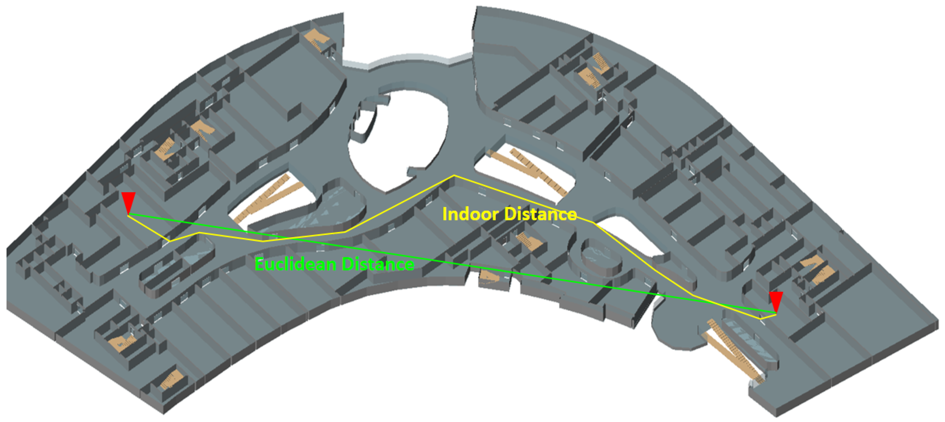
Indoor space composed of a number of architectural components, such as rooms, corridors, floors, wings and elevators, has more complicated structures than outdoor space. In order to compute the distance between two points in indoor space, we therefore have to consider the architectural structure, more precisely two factors: architectural components, such as walls, doors, stairs, etc., and the connectivity between indoor spaces, as shown in Figure 1. This means the information about indoor connectivity and architectural components is necessary to compute indoor distance. First, the indoor connectivity, called the indoor accessibility graph [13,23], has to be prepared, as we need a road network graph to compute distance on the road network. An indoor accessibility graph is represented as , where a node is a room or a space unit in indoor space and an edge represents the connectivity between two adjacent space units, for example via the door. The edge may contain any additional attributes such as the length of the connection.
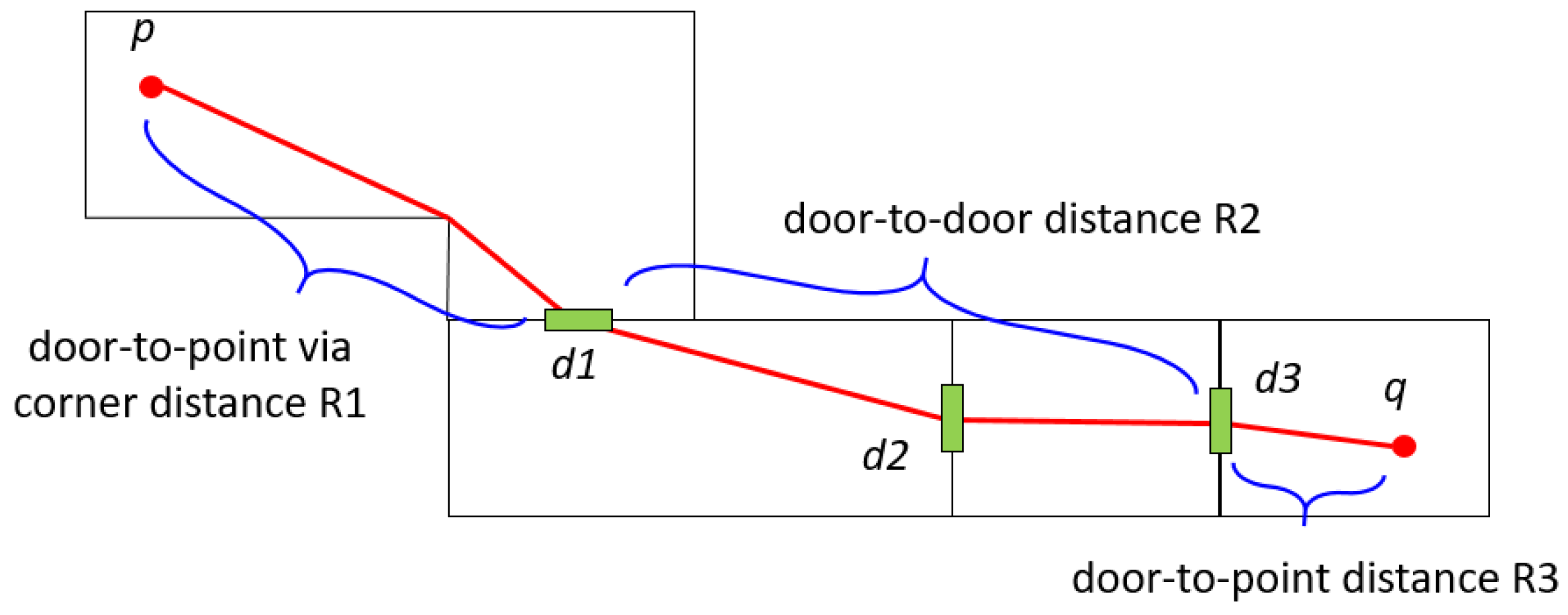
However, a simple edge connecting two nodes does not fully reflect the distance information particularly when the room connected to the edge has a big area or complicated geometry [24]. In order to overcome this problem, we need the geometry information of the room or space unit surrounded by architectural components, such as walls and doors. Once indoor geometry information is provided, the indoor distance is computed by dividing the total path into point-to-door and door-to-door distances as illustrated in Figure 2. In this figure, the path from point p to point q is divided into several sub-paths; the first sub-path from p to door , the second from to door and the third path from to q. While the distances from p to and from to q are called point-to-door distance, the distance from to door is called door-to-door distance. The point-to-door distance may be computed by line-of-sight [12] or the Minkowski sum [24], while the door-to-door distance can be easily computed by the shortest path algorithm with pre-computed door-to-door graph [12].
Since the vertical distance is not isotropic with horizontal distance, the indoor distance between two points on different floors is computed in different ways from the distance on the same floor. Furthermore, the vertical distance depends on the type of locomotion, whether elevators, stairs or escalators. For this reason, it is an alternative option to define indoor distance as the expected traveling time between two points rather than physical distance. More information such as type of locomotion and contextual information is required to compute the expected traveling time in addition to the accessibility graph and geometry of indoor space. Consequently, the standard indoor spatial data model should contain not only geometry, but also connectivity topology, semantic and additional information, such as context information, to support indoor distance computation.
3.2. Complex Structures of Indoor Space
The structure of indoor space is mainly determined by architectural structures that have unique properties. First, the indoor space consists of a number of cells surrounded by architectural components, such as walls, ceilings and floors, where each cell is separated from the others. Cells in indoor space are horizontally or vertically connected in sophisticated ways via specific types of architectural components like doors and stairs. Furthermore, indoor spatial properties, such as cell geometry and the connectivity structures between cells, differ depending on the type of buildings. For example, subway stations are normally composed of long hallways and platforms on different levels, while office buildings have normally a number of small office rooms connected via corridors.
Second, indoor spaces of complex buildings are often composed of areas with different purposes. For example, a shopping mall has a number of stores, warehouses, control rooms, cinemas, sports centers, subway stations, etc., each of which has unique requirements and functions. This complex buildings make the indoor space very complicated. Third, a single indoor space may be interpreted in different viewpoints. For example, an indoor space is partitioned into rooms and corridors, while it is also partitioned into public areas and private areas regarding its security levels. Since each interpretation forms a space layer with a proper partitioning criteria, an indoor space may have multiple space layers.
These complicated structures of indoor space are rarely found in outdoor space. Therefore, the indoor spatial data model should efficiently support complex structures of indoor space in terms of geometry, network connectivity and multiple interpretations.
3.3. Cell-Based Context Awareness
As claimed by an early work on ubiquitous and context-aware computing [25], the context has three important aspects; where you are, who you are with and what resources are nearby. The first and third aspects are related with the location of the user, which is normally represented as coordinates in outdoor space. However, it is more relevant to represent the location of the user in indoor space with the room number than coordinates, since the context is mainly determined by the type or function of the room. For example, staying in a class room for an hour has a totally different context from staying in a washing room for an hour.
One of the most basic functions of indoor context awareness services is therefore to identify the room or space unit where the user is currently located. In general, we call the unit of indoor space the cell, and rooms, corridors and staircases are examples of cells. Therefore, the indoor spatial data model should contain the notion of cell to support the indoor cell-awareness.
The indoor cell-awareness is defined as being aware of the cell where the user is currently located. In order to implement it, the indoor spatial data model has to provide the following functions. First, the boundary of the cell must be clearly defined either in two dimensions or three dimensions, such that we can easily discover the cell containing the point acquired from any indoor positioning method. For example, if the boundary geometry is represented by multiple surfaces, it is very hard to determine whether the point is within the cell or not. It is therefore required to represent the boundary of the cell by a closed geometry, such as a polygon in two-dimensional space or a solid in three-dimensional space.
Second, we need a function to correct the cell from noisy position data, since most indoor positioning methods contain a certain level of errors. For example, the reported accuracies of WLAN-based indoor positioning methods are mostly more than two meters [26], which is not sufficiently accurate to identify the current cell since the thickness of wall is much less than two meters. This function is similar with the map matching function of car navigation services, which corrects the current road segment from inaccurate GPS data. For this reason, we call this function indoor map matching. For the implementation of indoor map matching, the information about indoor network and cell types is required, as well as cell geometry, and should be included in the standard indoor spatial data model.
3.4. Integrating Multiple Datasets
For several reasons, the integration of multiple datasets is a fundamental requirement of indoor spatial data model. First, the integration of indoor and outdoor spatial datasets is crucial for seamless services between indoor and outdoor spaces. The indoor spatial data model should therefore provide a mechanism to integrate it with outdoor space. In order to implement a parking lot guidance service of car navigation for example, two datasets covering indoor and outdoor spaces, respectively, have to be integrated in a proper way.
Second, several standards for indoor spatial information have been developed, such as IFC, CityGML, KMLand IndoorGML, each of which has its strength and weakness. IndoorGML was designed to avoid duplication and conflicts with other standards and provides only a minimum set of functions of indoor spatial data that are missing in other standards. It is therefore recommended to integrate IndoorGML data with other standards for compensating its weakness and taking advantage of strengths from other standards.
Third, it is often necessary to interpret and configure a single indoor space from multiple viewpoints, which is similar to the multiple layer structure of the conventional geospatial data configuration for outdoor space. For example, the layout of an indoor space is given as a topographic map, while the map of CCTV coverage is also useful for security purpose.
In general, there are two approaches for the integration. The first approach is a physical integration of multiple datasets of different standards into a single dataset. For example, CityGML provides a mechanism called ADE (Application Domain Extension) [3], which extends CityGML to include additional information. A spatial data model in another standard may be re-defined as an ADE of CityGML, and a conversion process from a dataset to CityGML ADE is required.
The second approach is to link multiple datasets in different standards via external references without physical integration. For example, each feature in a dataset of a standard data model has an external reference or foreign key to a feature in another dataset of a different standard data model and vice versa. This approach is simple and practical when the correspondence between features in and is one-to-one. Thus, the standard data model should support the integration via the extension mechanism or an external reference.
4. Basic Concepts of IndoorGML
In this section, we study the basic concepts of OGC IndoorGML developed to meet the requirements of standard indoor spatial data model listed in Section 3. Note that most of this section is a summary of the IndoorGML standard specification found in [4].
4.1. Cellular Space Model
IndoorGML is an application schema of OGC GML (Geography Markup Language) 3.2.1 [18], which is an XML grammar for expressing geographical features, based on the spatial data model in ISO 19107 [5]. As mentioned in Section 3.3, indoor cell-awareness is a basic requirement of the indoor spatial data model. For this reason, the key concept of IndoorGML is based on the cellular space model. Cellular space is defined as follows:
Definition 1 (Cellular space).
A cellular space of a space is defined as a set of cells such that, for any pairs of cells , ,
- 1.
- ,
- 2.
- ⋃ and
- 3.
- each cell c has its cell identifier .
No overlapping between cells is allowed, and the union of all cells is a subset of the given indoor space. This means that there may be shadow areas, which are not covered by any cell, and every position does not necessarily belong to a cell.
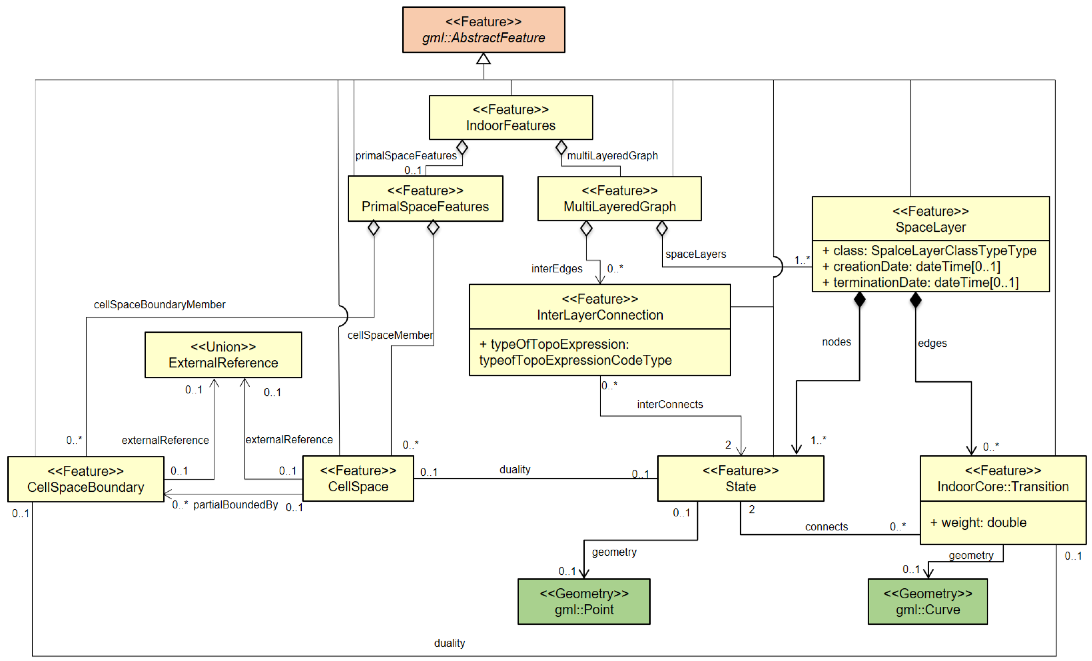
Based on the cellular space model, IndoorGML provides four main concepts to satisfy the requirements listed in Section 3; cell geometry, topology between cells, cell semantics and multi-layered space model. This cellular space is given as a UML class diagram depicted in Figure 3, which is the core module of IndoorGML. In the following subsections, we will see how each of the concepts is implemented in IndoorGML.
4.2. Cell Geometry
The cell is a basic unit of the cellular space model, and its geometry is defined as a two- or three-dimensional spatial object. Since IndoorGML is based on the geometry model of ISO 19107 [5], the cell geometry can be either a surface or a solid defined in ISO 19107, but there are three options to represent cell geometry in practice;
- Option 1, no geometry: The first option is to exclude any geometric properties from IndoorGML data and to include only topological relationships between cells, which will be explained in the next subsection.
- Option 2, geometry in IndoorGML: The second option is to represent its geometry within IndoorGML data by geometric types defined in ISO 19107. For example, the three-dimensional geometry of a cell is defined as a solid of ISO 19107. Note that the geometry of the cell is an open primitive as defined in ISO 19107, which means that the boundary of the cell geometry does not belong to the cell. This definition is consistent with the non-overlapping condition of the cellular space defined in Section 4.1.
- Option 3, external reference: The third option is to include external references to the object in another dataset that contains geometric data. For example, a cell in IndoorGML data only points to an object in CityGML via the GML identifier that contains geometric properties.
These options are not exclusive and may be combined together. For example, while no geometry is included in an IndoorGML data (Option 1), it contains external references to objects in other dataset (Option 2). Furthermore, the geometry defined in IndoorGML is not necessarily identical with the geometry of the corresponding object in other dataset.
4.3. Topology between Cells
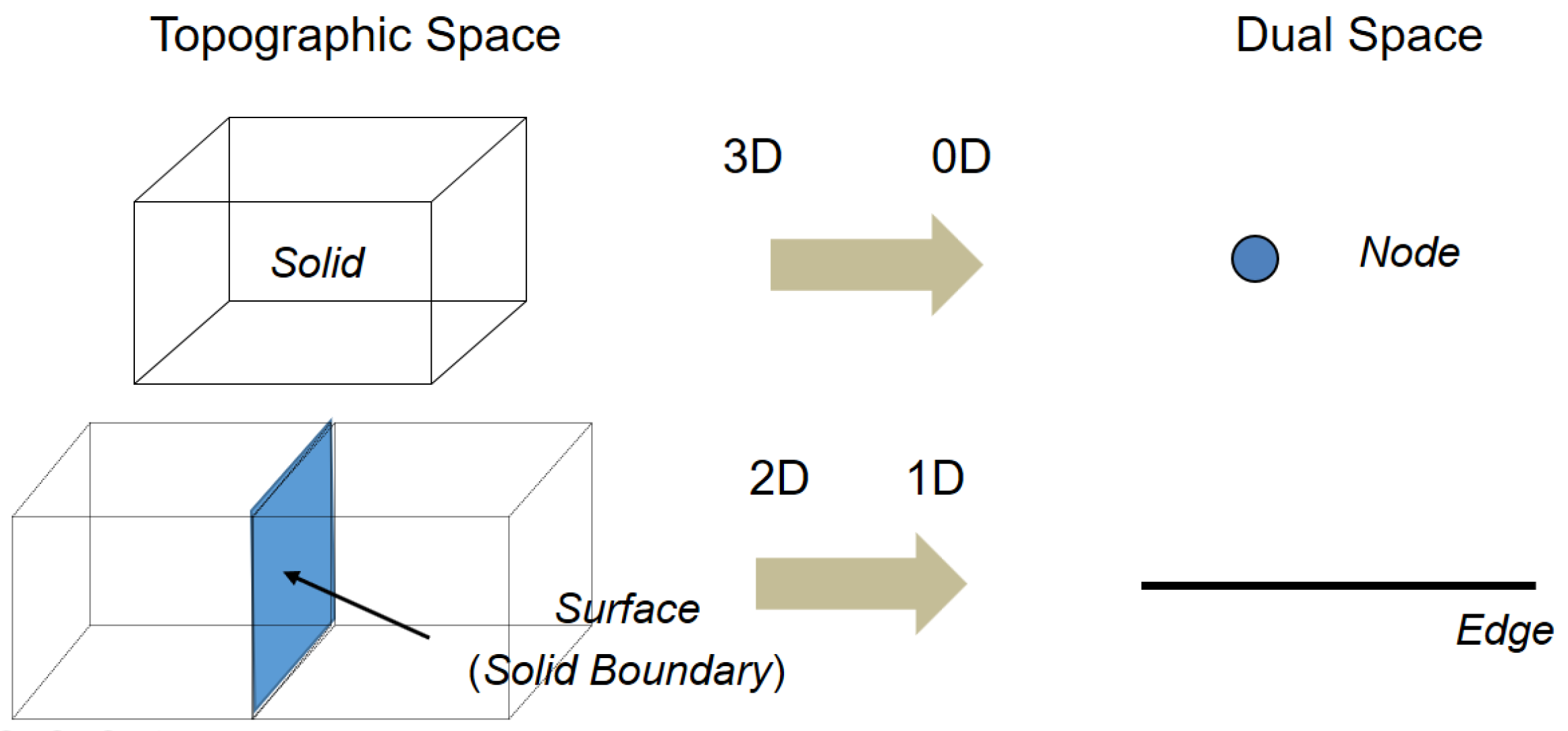
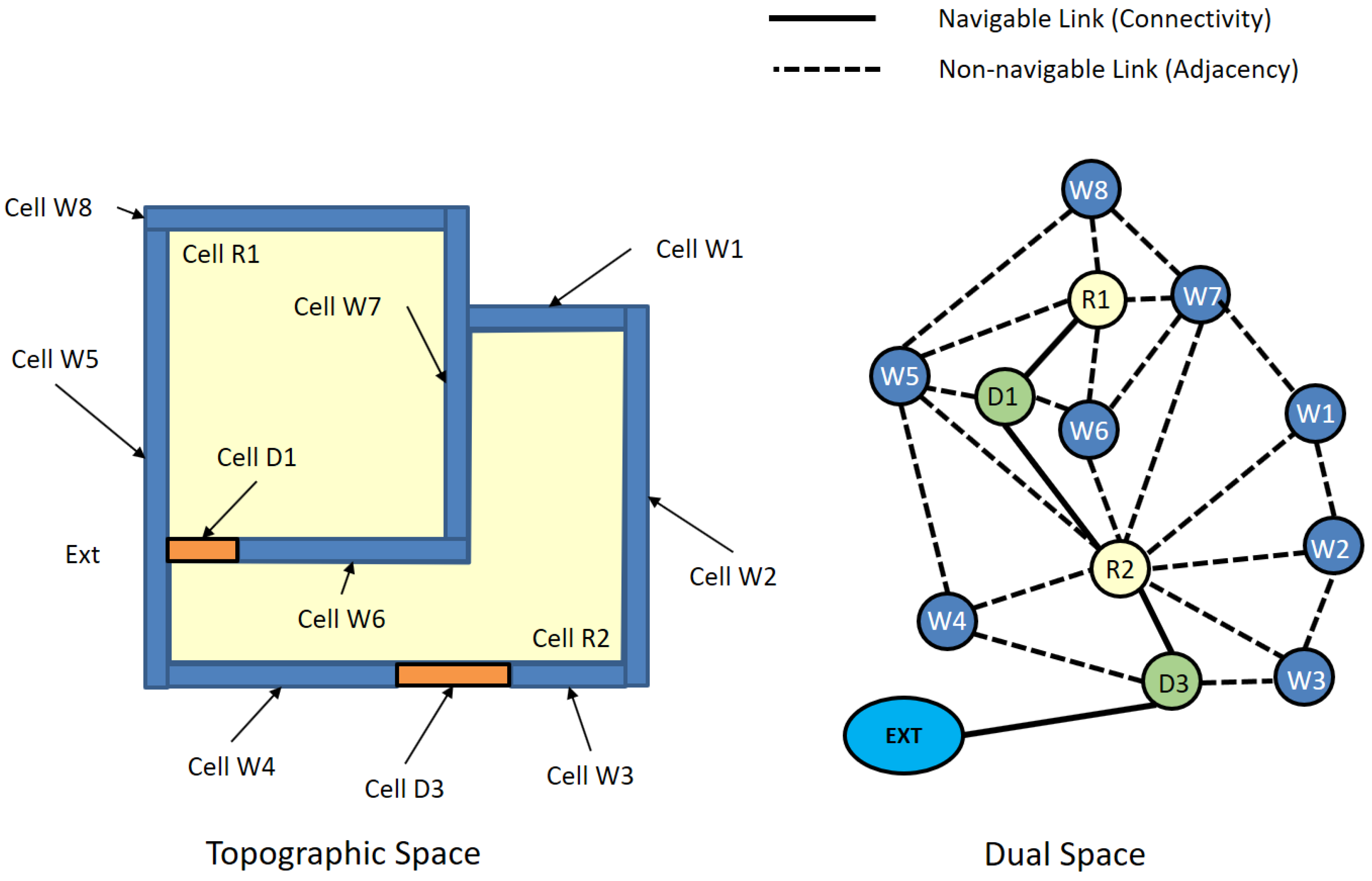
Once cells are determined with their identifiers and geometric properties, we need to describe the topological relationship between cells, which is essential to most of the indoor navigation applications. The topology between cells in IndoorGML is basically derived from topographic layout of indoor space by Poincaré duality [27]. As illustrated in Figure 4, a k-dimensional object in the N-dimensional topographic space is mapped to a -dimensional object in the dual space.
This means that a three-dimensional cell in topographic indoor space is transformed to a zero-dimensional node, and a two-dimensional boundary surface shared by two cells is transformed to a one-dimensional edge in the corresponding dual space. The set of nodes and edges transformed from the topographic space by Poincaré duality results in a topological graph connecting adjacent cells in indoor space. Figure 5 shows an example of an adjacency graph derived from a topographic indoor space. From the adjacency graph, we can also derive a connectivity graph considering the type of edges in the adjacency graph. If an edge indicates the boundary of a door, then two ending nodes of this edge are connected via the door. We may define more attributes on the edge to represent additional information, such as distances, directions and types of doors, etc.
There are two options to represent the graph derived from topographic space in IndoorGML. The first option is to include the geometries of the node and edge as a point and a curve, respectively. We call the graph with geometric properties geometric graph. The second option is to represent the graph without any geometric properties, which is called the logical graph. However, in most applications of indoor navigation, we need geometric data to calculate indoor distance. There are several studies [12,13] to compute the optimal path and its distance between two points in indoor space, and we will discuss indoor distance in Section 6.
4.4. Cell Semantics
Since every cell in indoor space has its proper function and usage, we need to specify the semantics of cells. In the current version of IndoorGML, we classify the types of cells in terms of indoor navigation and expect that other classifications would be necessary for different applications, such as indoor facility management. Figure 6 shows the current classification of cells in IndoorGML for indoor navigation. In particular, the anchor node in Figure 6 represents a gate or entrance of building and allows connecting indoor and outdoor spaces. Besides the classification of cells shown in Figure 6, more detailed classification of cells and cell boundaries are also defined as attributes. For example, the code list given by OmniClass [28] can be used, which defines the hierarchical classification of features in the building.
4.5. Multi-Layered Space Model
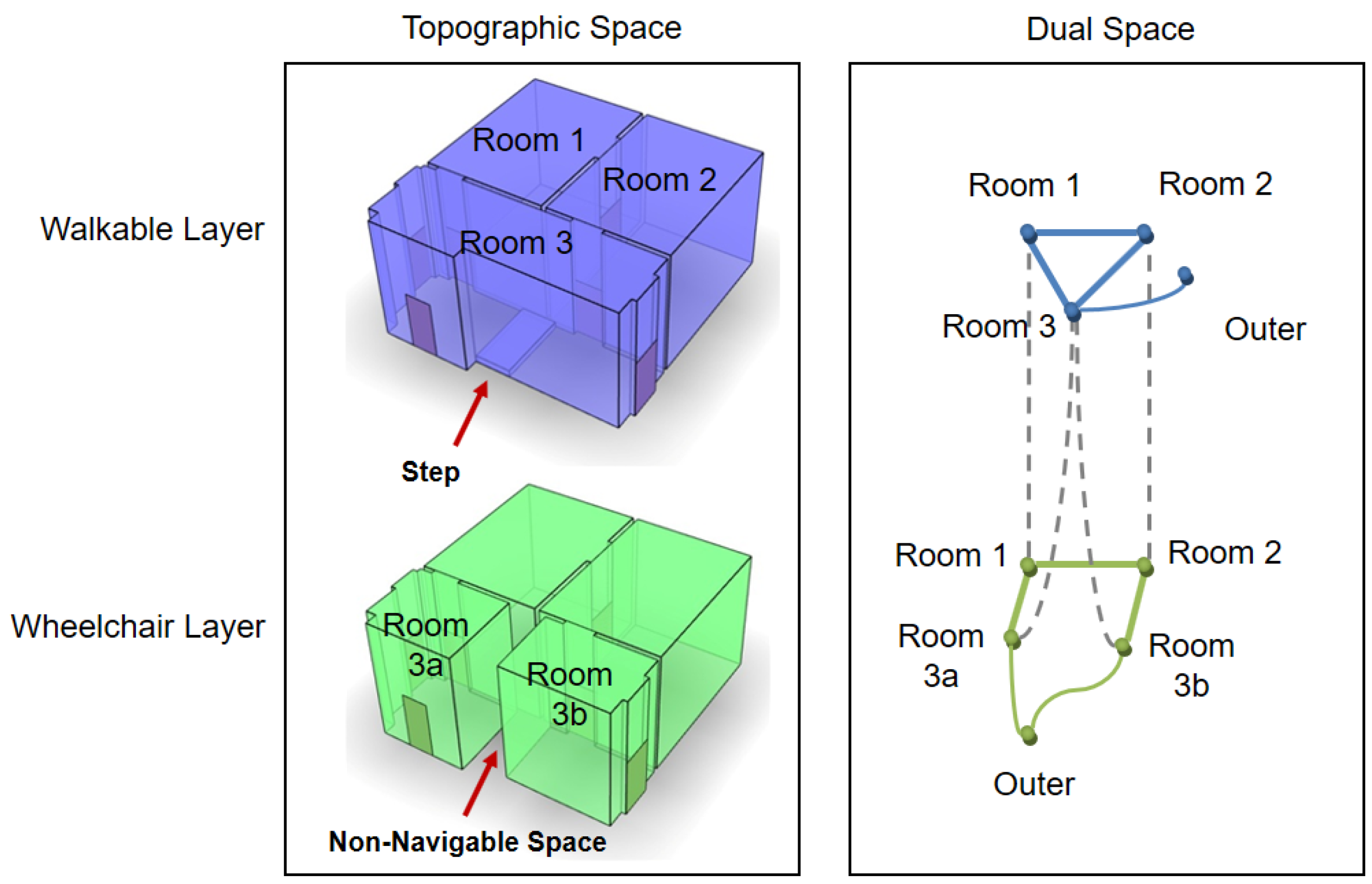
As briefly mentioned in Section 3.4, the same indoor space can be interpreted and represented in different ways. In IndoorGML, a mechanism, called the multi-layered space model is offered to represent an indoor space by overlaying different interpretations [4,29]. Each interpretation corresponds to a cellular space layer with its own geometric and topological properties. For example, there are two different layer configurations of an indoor space due to a step in Room 3, as shown in Figure 7; the walkable layer and wheelchair layer.
Since each layer forms a cellular space, it includes the geometries of cells, topologies between cells given as a graph and cell semantics. In addition to simple aggregation of cellular space layers, a special type of edge, called inter-layer connection, is also offered in IndoorGML to represent the relationships between nodes in different layers. In Figure 7, we have Room 3 in the walkable space layer corresponding with Room 3a and Room 3b in the wheelchair layer because Room 3 is partitioned into Room 3a and Room 3b due to a step. The multi-layered space model is also useful for many applications, such as in describing the hierarchical structure of indoor space or in tracking moving objects from sensor data. Further detailed discussion is found in [29].
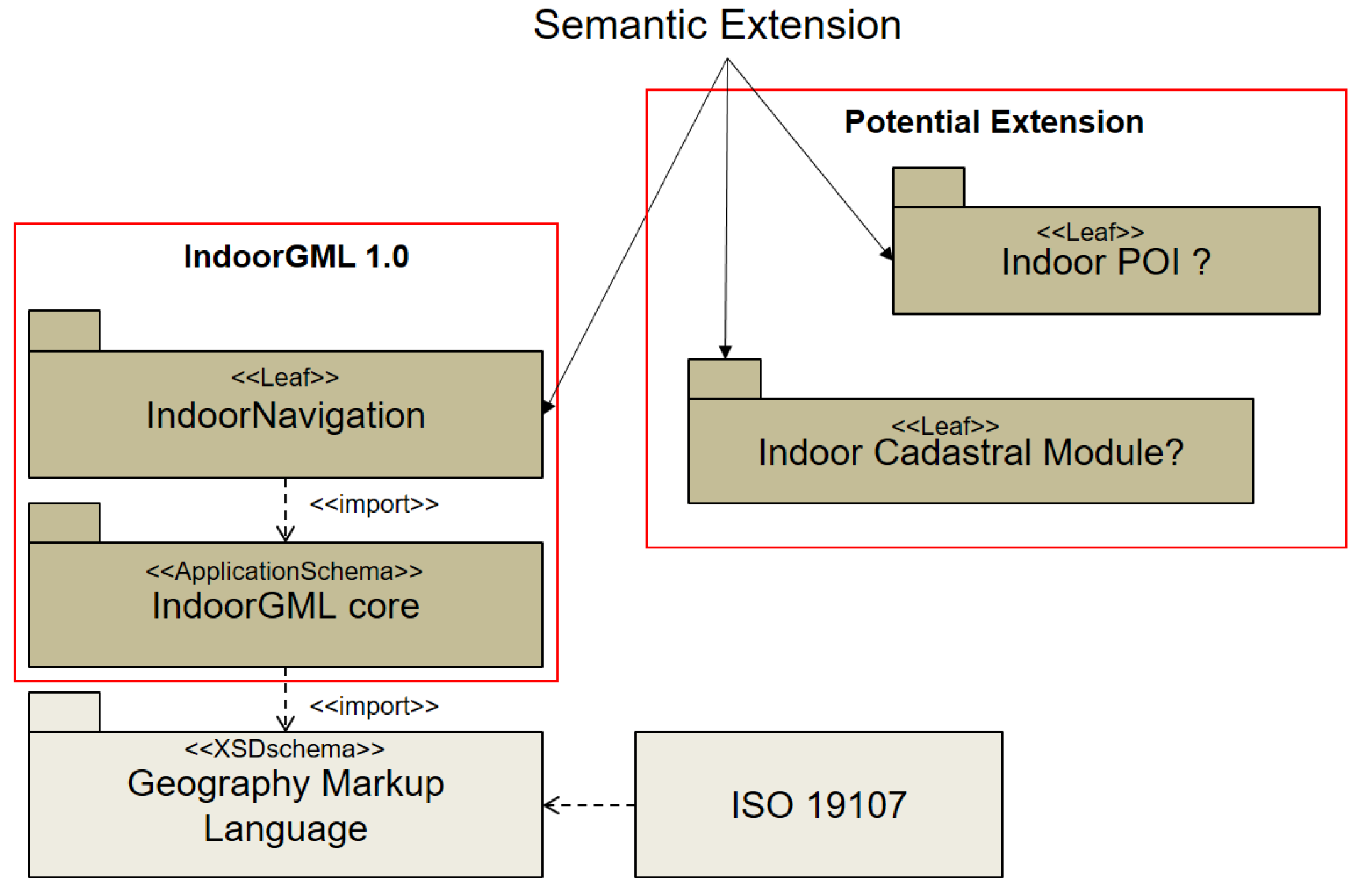
4.6. Modular Structure of IndoorGML
For the sake of extensibility, IndoorGML has a modular structure as shown in Figure 8. The core module of IndoorGML contains the data model for cell geometry, topology and the multi-layered space model. The indoor navigation extension model, which provides the semantic extension model for indoor navigation, is so far the only extension module defined on the top of the core model. Many other extension modules may be defined depending on applications. For example, the indoor cadastral model is a candidate extension of IndoorGML [30].
4.7. Implementation of IndoorGML Core Module
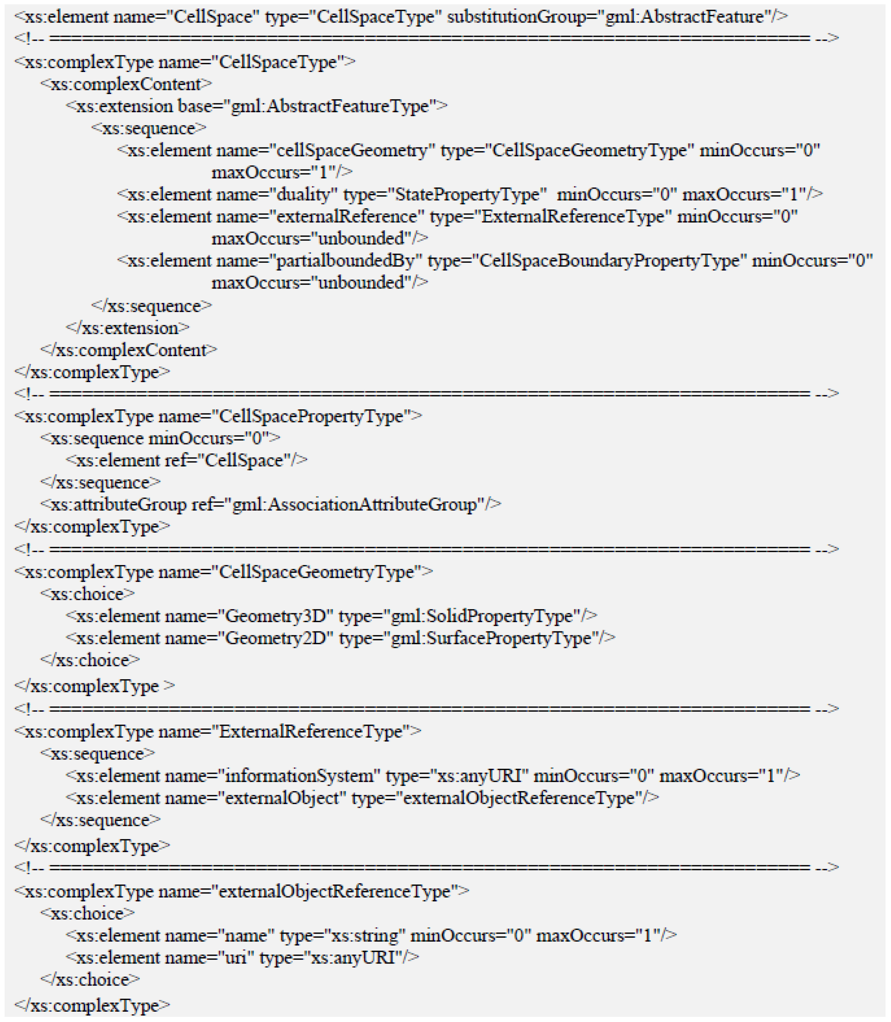
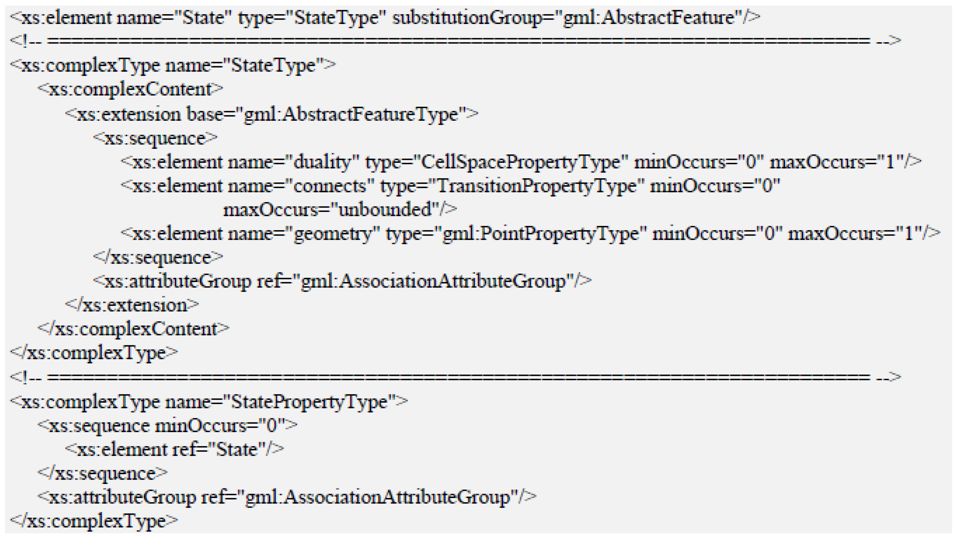
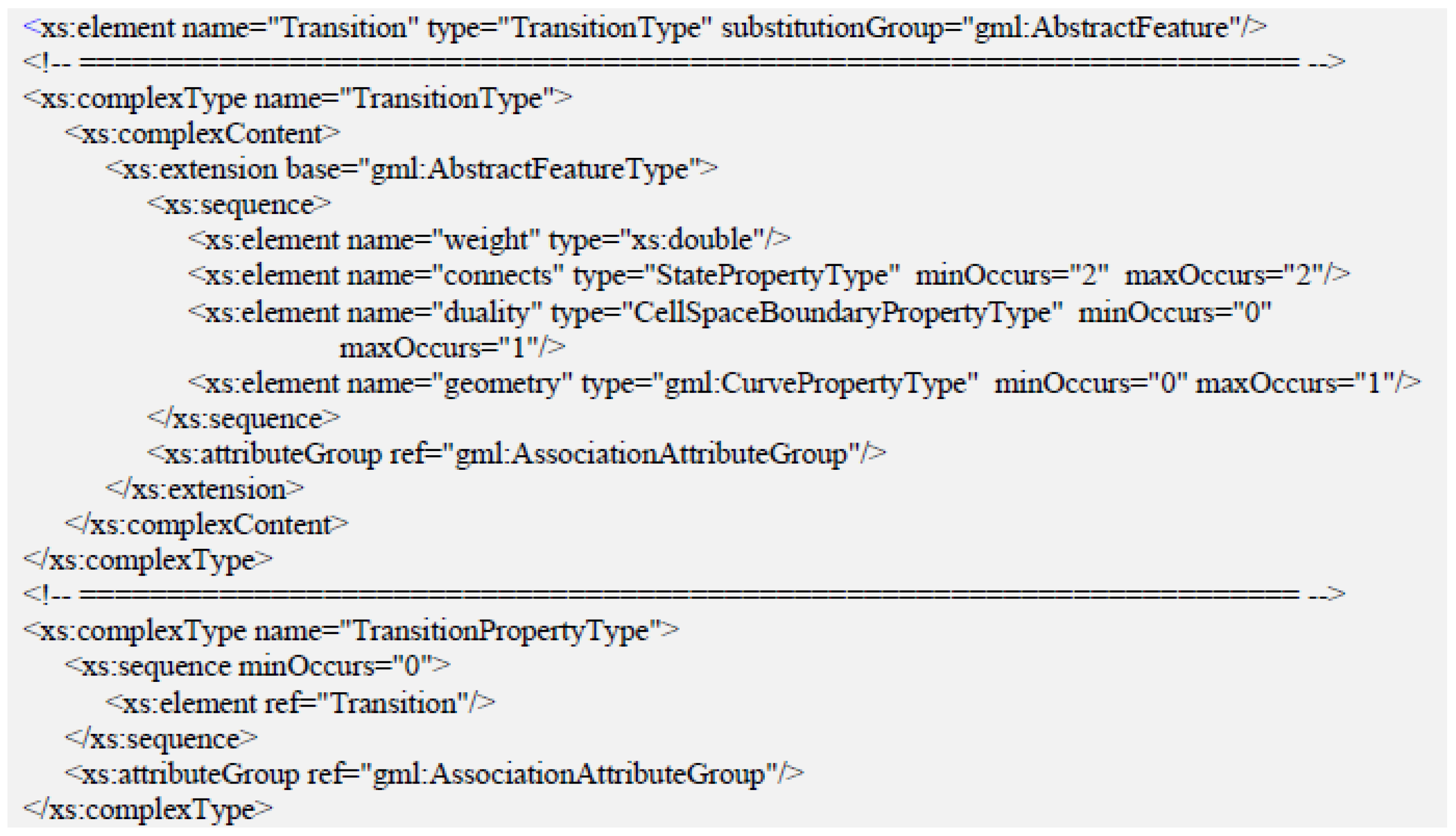
Since IndoorGML provides not only a standard indoor spatial data model, but also a format for data exchange, it defines an application XML schema based on GML 3.2.1 in addition to the UML class diagram. The UML class diagram in Figure 3 is therefore expressed in a XML schema, which defines the structure of XML data for IndooGML. The XML schema for the IndoorGML core module includes four basic types: State, Transition, CellSpace and CellSpaceBoundary. While CellSpace and CellSpaceBoundary belong to the basic units of the indoor primal space; State and Transition correspond to CellSpace and CellSpaceBoundary of the dual space for the connectivity topology of indoor cellular space. The schemas are given in Figure 9, Figure 10, Figure 11 and Figure 12, respectively.
CellSpace defines a basic unit type of the cellular indoor space model, such as room, corridor and hall. It basically contains a GML identifier as a gml:AbstractFeature object [18] with attributes. As defined in Figure 9, it may also contain a reference to an external object, which may provide additional information. The geometric type of CellSpace may be either a solid or surface depending on the dimensionality of the space or may not contain any geometry as discussed in Section 4.2. While CellSpace represents a cell in indoor space, CellSpaceBoundary defines the boundary geometry of a CellSpace object, and its geometry may be a surface or curve depending on the dimensionality. Since CellSpace and CellSpaceBoundary represent two basic unit types in primal space, further extensions to these basic types can be defined as subclasses with a given semantic context. For example, the feature types for indoor navigation can be defined as subclasses of CellSpace and CellSpaceBoundary for an extension.
State and Transition define the feature types of dual space corresponding with CellSpace and CellSpaceBoundary in terms of connectivity topology. They are useful in indoor navigation applications such as optimal routing computation or indoor distance computation. Additional information may be given as attributes of these feature types.
5. Cell Determination in IndoorGML
One of the fundamental issues in utilizing IndoorGML, which is however not explicitly addressed in the standard document of IndoorGML, is how to determine the granularity of cells and partition a given indoor space into cells. In this section, we discuss several issues about the cell determination and subspacing.
5.1. Cell Determination and Subspacing
From the topographic viewpoint, it is relatively easy to determine cells and the granularity of cells. However, in addition to the topographic viewpoint, the following cases should be considered to determine the granularity of cells and partition a space into subspaces. More detailed criteria are found in [30,31,32,33,34]:
- different properties: if a space has different properties such as kitchen area and living room, it is desirable to partition it into two cells with virtual boundaries.
- big space as a cell: if a space is too big, like a long hall-wall or a big convention hall, it is recommended to split it into smaller subspaces.
- sensor coverages: it is also possible to divide a space in terms of sensor coverage, such as CCTV viewshed or WiFi and RFID coverages [29].
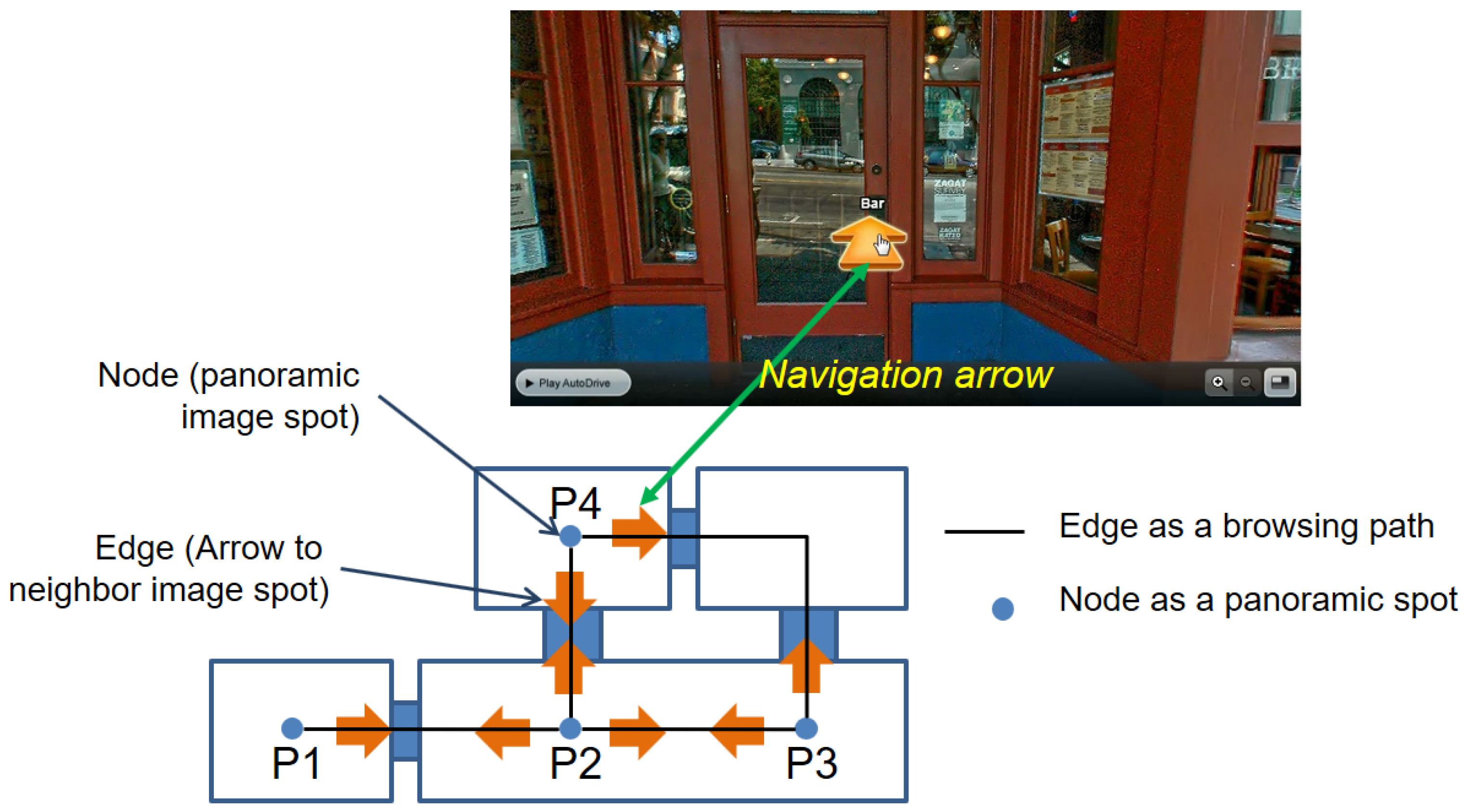
- cell without spatial extent: while cells have spatial extents in most cases, there are also cases where no spatial extent is necessarily required except a point. For example, each image spot in a panoramic image service shown in Figure 13 is represented as a cell without spatial extent except a point. Note that the panorama spot image layer is defined as a separate space layer of IndoorGML, and we define inter-layer connections with the cells in the topographic layer. We also assume that each navigation arrow connecting two image spots is considered as an edge in the connectivity graph for the panorama spot image layer, as in Figure 13.
5.2. Thick-Wall Model vs. Thin-Wall Model
An indoor space is differently represented depending on how to handle the thickness of walls. If we ignore the thickness, the wall is represented simply either as a surface in three-dimensional space or a polyline in two-dimensional space, as shown in Figure 5 in Section 4.3. The adjacency graph contains only the edges between , and the external space in Figure 5. We call this representation model the thin-wall model. On the contrary, if we take their thickness into consideration, the walls and doors are also considered as cells, and the adjacency between rooms and wall, such as and , is included in the adjacency graph, as shown in Figure 14.
By extracting only the navigable parts of the graph, we can derive the accessibility graph of indoor space by removing the non-navigable cells such as walls and the non-navigable links such as edge connecting and , depicted as dotted lines in Figure 14.
5.3. Representing Hierarchical Structures
Most indoor spaces have hierarchical structures. For example, a building complex consists of several buildings, each of which is also divided into the east wing and west wing, and each wing is composed of multiple floors, and so on. An efficient way to represent hierarchical structures of indoor space was introduced in [16]. The authors of this paper proposed a simplified form of hierarchical graph for indoor space as defined below:
Definition 2 (Hierarchical graph).
A level- hierarchical graph H with regard to a level-l base graph is defined by a complete partitioning of G into k () non-empty, connected set of nodes . Each node induces a subgraph with . Each of these subgraphs, in turn, corresponds to a node in the hierarchical graph H. Edges in H correspond to edges in G between nodes and of two different subgraphs and .
It is possible to redefine the hierarchical graph for indoor space by the multi-layered space model of IndoorGML [35]. First, we define the single-layered graph and the multi-layered graph using the multi-layered space model as follows:
Definition 3 (Single-layered graph).
A single-layered graph is a graph , where:
- -
- and
- -
- .
Definition 4 (Multi-layered graph).
A multi-layered graph is a graph that consists of multiple single-layered graphs and a set of inter-layer connections (), which are a special type of edge connecting two layers, where:
- -
- ,
- -
- , and
- -
- .
Then, the hierarchical graph is considered a specific type of multi-layered graph connecting -th and -th layers as defined below:
Definition 5 (Hierarchical graph of IndoorGML).
A hierarchical graph is a multi-layered graph with inter-layered connections between and layers such that:
- -
- ,
- -
- ,
- -
- ,
- -
- If
where denotes the topological relationship between two cells .
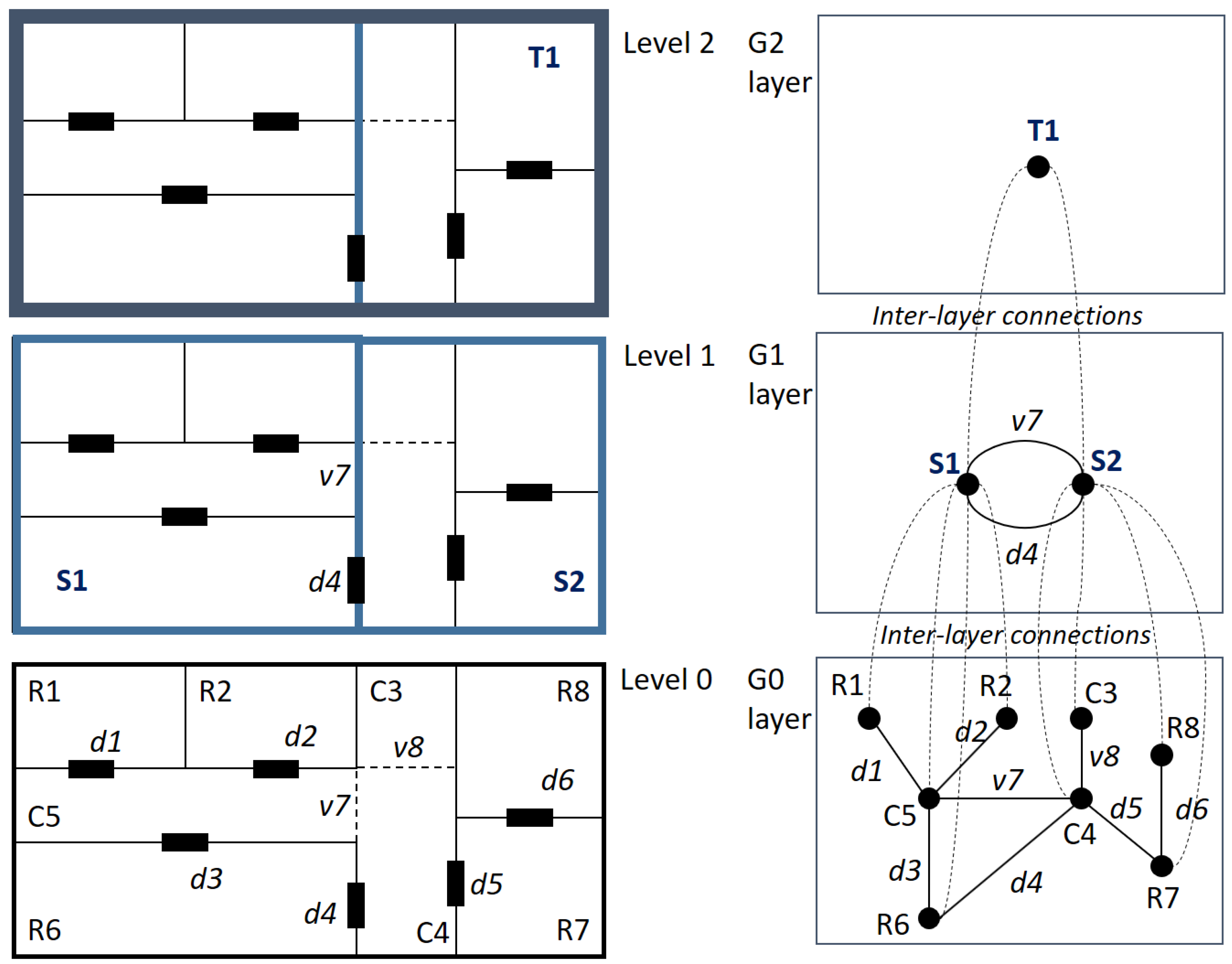
Note that each level of the hierarchical graph indicates a layer of a multi-layered graph; therefore, is the single-layered graph of the bottom level. The highest level , namely the root graph of the hierarchical graph, contains only a node without edge, where h is the height of the hierarchical graphs. Figure 15 shows an example of the hierarchical structure for an indoor space by the multi-layered space model of IndoorGML. and in Level 1 are the aggregations of and in Level 0, respectively. is the entire indoor space as the aggregation of . Then, the layer indicates the base graph of the indoor space; is the next level layer of the hierarchy; and is the layer for the root level. The relationships between layers are given via inter-layer connections. Note that the topological properties of inter-layer connections in Figure 15 are INSIDE.
6. Computing Indoor Distance Using IndoorGML
As mentioned in Section 3.1, the distance is one of the fundamental spatial properties. However, the computation of distance in indoor space differs from outdoor space due to the complex structures of indoor space as discussed in Section 3.2. In this section, we discuss how to compute indoor distance using IndoorGML.
6.1. Horizontal Distance
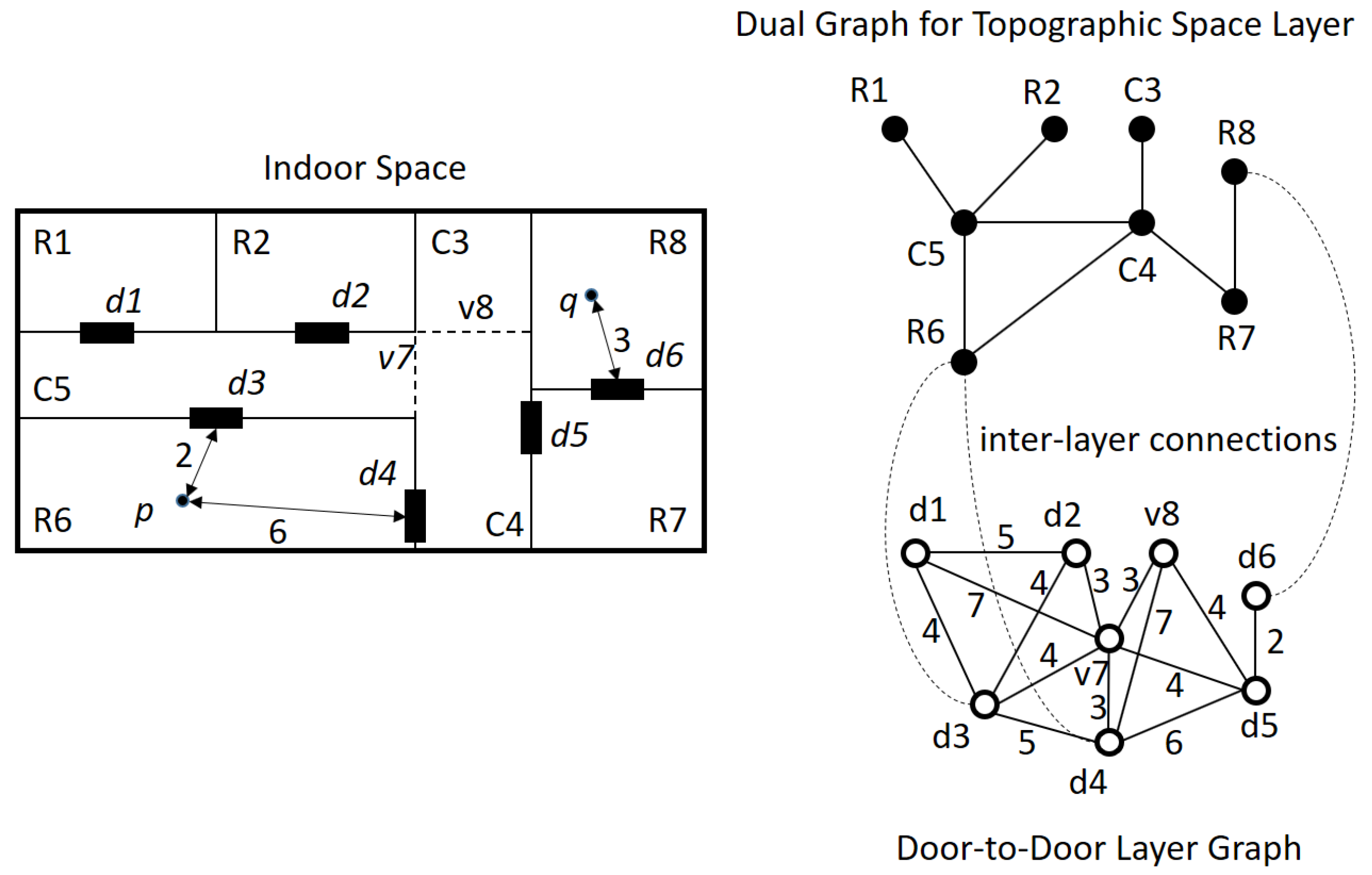
First, we discuss the horizontal distance, which is the distance between two points on the same floor. The distance between two points p and q in Figure 16 is divided into point-to-door distance and door-to-door distance. In order to compute the point-to-door and door-to-door distances, we prepare two space layers: the topographic layer and the door-to-door layer of IndoorGML, as the right part of Figure 16. Note that the door-to-door graph is a weighted graph so that the weight of the edge represents the distance between two doors. Then, we compute the horizontal distances using the topographic layer, door-to-door layer graph and inter-layer connections of IndoorGML data. The Algorithm 1 is given as below.
| Algorithm 1. Indoor_Distance () |
| Input: |
| - topographic layer C: set of indoor cells with cell geometry, |
| - door-to-door (D2D) layer graph , |
| - multi-layered space model graph , and |
| - starting and ending points |
| Output: horizontal indoor distance |
| Begin |
| 1. the cell containing point p; |
| 2. the cell containing point q; |
| 3. where L is the set of inter-layer connections; |
| 4. ; |
| 5. ; |
| 6. ; |
| 7. is the shortest path from to from D2D layer graph; |
| 8. where , and ; |
| 9. return ; |
| End |
In the above algorithm, and denote the i-th and j-th doors belonging to the cells containing p and q respectively, is the distance between p and within the cell and means the length of path p.
In Line 1 and Line 2 of the algorithm, we find the cells containing p and q, which are R6 and R8, respectively, in Figure 16, using the cell geometry data in the topographic layer. The doors of R6 and R8 are found as and from the inter-layer connections of the multi-layered space model in IndoorGML in Lines 3 and 4. Then, we compute the door-to-point distances from p and q to each door in and respectively using the cell geometry of IndoorGML for Lines 5 and 6. The door-to-point distance within a cell can be computed by the shortest path in a polygon algorithm in computation time where n is the number of vertices in the cell [36]. Then the results are and . We also compute the door-to-door shortest paths connecting and using the door-to-door layer graph in Line 7. Two shortest paths are obtained from the door-to-door layer graph: and , where and . Then, the horizontal distance is the sum of the door-to-point distance and door-to-door distances in Line 8, and the route with the minimum distance is ; and its distance while the distance of the alternate route is 17. We can also compute the horizontal indoor distance with the thick-door model in the same way.
6.2. Vertical Distance
We have to consider an additional factor in computing the distance between different floors, called vertical distance. Vertical distance, for example through stairs, is not an isotropic measure with the horizontal distance due to different speeds, energy consumptions, transportation modalities, and so on. A rigorous survey on vertical distance is found at [32]. Figure 17 shows an example of the multi-layer configuration with topographic and door-to-door layers to compute vertical distance via the elevator. The topographic layer and door-to-door layer configurations are shown in the left part and the right part of the figure, respectively. Note that the red dotted lines represent the inter-layer connections between the cell at the i-th floor and the door connecting the i-th floor to the elevator shaft cell, while the blue dotted lines indicate the inter-layer connections between the door at the i-th floor and the elevator shaft cell. The topological relationships of all inter-layer connections in the figure are MEET in this case.
However, the weight of each vertical edge in the door-to-door graph given at the right part of Figure 17 must be assigned differently from horizontal edges. Furthermore, the door-to-door graph may be directed since up-speed differs from down-speed. Additionally, the weight of the edge also depends on the vertical transportation modality, whether elevators, stairs, escalator or ladders. When we prepare the door-to-door graph layer of IndoorGML data, all of these factors must be reflected to compute the correct vertical indoor distance. Once the topographic layer and door-to-door layer are prepared, we apply Algorithm 1 given in Section 6.1 to compute the indoor distance, no matter whether it is vertical, horizontal or hybrid distance.
In this paper, we do not consider more complicated indoor structures, such as the Mercedes-Benz Museum in Stuttgart or Guggenheim Museum in Manhattan, New York City, which have spiral structures, where vertical distance is not clearly separable from horizontal distance. We expect that the indoor distance for these special cases could be computed by Algorithm 1 in Section 6.1 with proper configurations of topographic and door-to-door layers.
6.3. Multi-Modal Distance
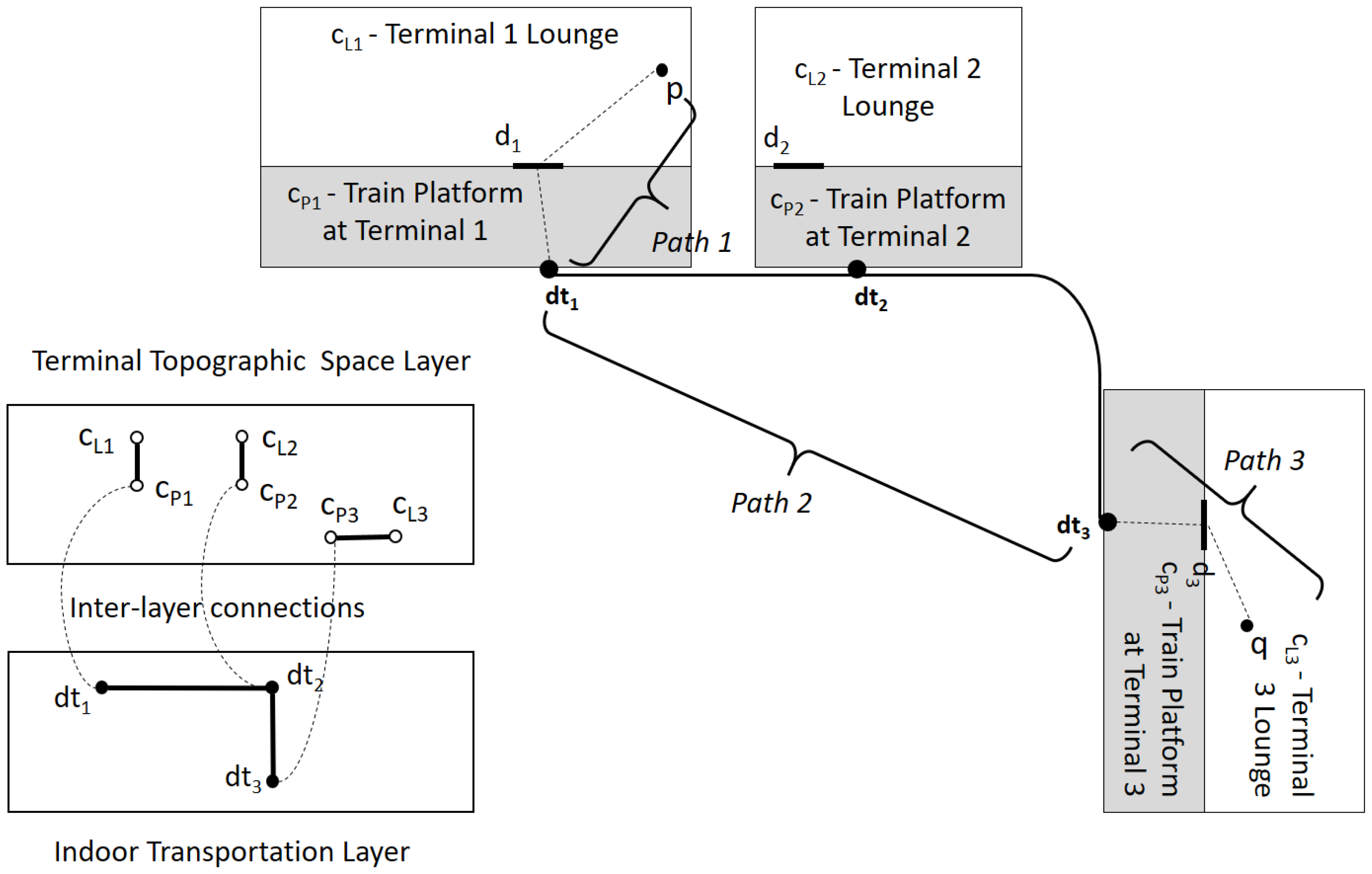
The transportation modality is an additional factor to consider in computing indoor distance. For example, when we compute an indoor distance between two points in different terminals of an airport, connected via the inter-terminal railway, we have to integrate multi-modal transportation that comprises horizontal movements, vertical movement via escalators and the inter-terminal railway. In this case, the traveling time is a more proper metric of indoor distance than the physical distance between two terminals. First, we provide an additional layer for indoor transportation, as well as the terminal topographic layer, as shown in Figure 18 in a similar way with door-to-door layer. Note that the weight of the edge in the indoor transportation layer graph is given as the traveling time between two nodes. In order to compute the traveling time from point p in the Terminal 1 lounge to q in the Terminal 3 lounge, we integrate the travel time of three paths, Path 1, Path 2 and Path 3 in Figure 18. The indoor distance is computed in a similar way given in the previous subsection by replacing the door-to-door layer graph with the indoor transportation layer graph and applying Algorithm 1.
7. Context-Awareness by IndoorGML
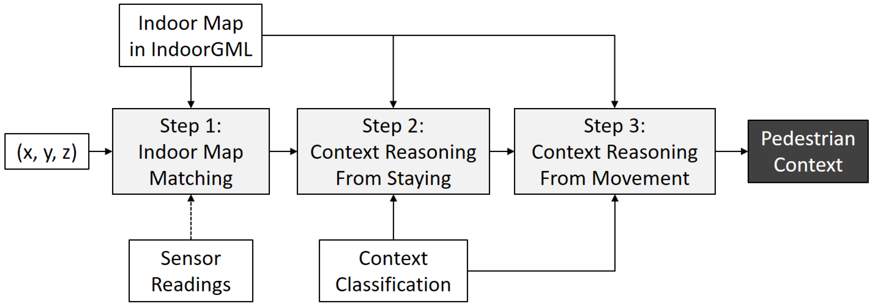
As addressed in [1], the context-awareness is one of the major requirements for indoor spatial services. In this section, we investigate how to implement the context-awareness with IndoorGML. A first observation on the context-awareness in indoor space is the fact that the context of a pedestrian is mainly determined by: (1) the cell where she/he stays; (2) the time interval of staying in each cell; and (3) the sequence of cell visits; which are summarized as the following process:
- Step 1: indoor map matching:
- Step 2: context reasoning from staying interval:
- Step 3: context reasoning from visit sequence:
where p is a point collected from any indoor positioning device, c is a cell, I is a time interval, is a sequence of visit and is a context. , and are the functions for indoor map matching, context reasoning function from staying interval and context reasoning function from visit sequence, respectively. This process is summarized by Figure 19. In the subsequent sections, we will discuss each step.
7.1. Indoor Map Matching by IndoorGML
The first step of indoor context-awareness is to identify the cell where a pedestrian is staying. The indoor position is given as either a point or a sensor coverage depending on the type of indoor positioning methods. In any case, the position acquired from indoor positioning has inevitably a certain level of errors as mentioned in Section 3.3, which may yield incorrect results of indoor map matching. With the information in IndoorGML, we can improve the accuracy of indoor map matching as the following process (Algorithm 2):
| Algorithm 2. Indoor_Map_Matching_From_Point () |
| Input: |
| - topographic layer C: set of indoor cells with cell geometry, |
| - accessibility graph , |
| - current point and past trajectory , and |
| - sensor readings S. |
| Output: current cell c |
| Begin |
| 1. Find containing ; |
| 2. Correct by analyzing the past trajectory and accessibility graph ; |
| 3. Improve by analyzing other sensor readings; |
| 4. return c; |
| End |
Note that this algorithm presents only the key idea at the conceptual level but not at the implementation level. First for Line 1 of the algorithm above, we can find the cell containing the current position of pedestrian by point-in-polygon or point-in-polyhedron algorithm with the cell geometry information given by IndoorGML. Second, we find the most probable cell by analyzing the indoor accessibility graph given in IndoorGML and the past trajectory. For example in Figure 20, is the current position and is the position at time where they are collected by an indoor positioning method. Then, the probability that the current cell is in is very low, since the indoor distance from to exceeds the maximum distance that a normal pedestrian could move within the time interval . The probability that the current cell is is higher than , and the most probable path is , depicted in white circles in the figure. In this paper, we do not discuss the implementation detail for Line 2, but several approaches such as the hidden Markov model may be able to estimate the probability of each route [37].
While the algorithm is for indoor map matching from a point, we can modify it for the case that the current position is given as a coverage. In this case, the current cell ( in the algorithm) is given as multiple cells that overlap with the sensor coverage. Then, Step 2 should be modified to process multiple candidate cells.
In addition to past trajectory, we can also improve the accuracy by analyzing other sensor readings from smartphone such as accelerometer and digital compass for Line 3 of the algorithm. For example, if the speed of a pedestrian is high, she/he is probably running in a hallway rather than a washing room. Additionally, the direction data are also useful to estimate the current cell. If the direction of the movement at is given as the arrow in Figure 20, then the probability that the current cell is in is even smaller because it is impossible to move along the arrow direction due to the wall between and .
7.2. Context Reasoning from the Staying and Visit Sequence
Once we find the cell where a pedestrian is staying, more useful context on the pedestrian can be also derived from staying and visiting sequences. For example, if 40 students are staying in a classroom for an hour with a professor, they are most probably attending a class. If a person is staying in a washing room for an hour, she/he may have a serious problem. We can deduce the context of a pedestrian from the information about the current cell and the staying time interval. The framework of the context reasoning can be given as a tuple:
where S is a set of staying tuples , is a cell classification, is a context reasoning function from staying data and is the target context classification. IndoorGML provides the semantics for cell classification based on OmniClass [28], which defines a comprehensive classification of building components in terms of functions and spaces.
For the same reason, the visiting sequence is also useful data to derive the context of pedestrians. For example, we may expect that if a pedestrian visits only shops for baby clothes in a shopping mall, it is probable that she/he intends to buy something related to baby clothes. If she/he returns to the first shop of the visit, it is highly probable that she/he would buy something at this shop. The framework for the context reasoning with a visiting sequence can be also specified as a tuple:
where V is a set of visiting sequence of pedestrian. is a context reasoning function from the visiting sequence. Since the implementation of context reasoning functions and the classification of pedestrian context are dependent on application domains and beyond the scope of this paper, we leave these issues as future works.
8. Conclusions
With the increasing demands for indoor spatial information, the standard indoor spatial data model becomes a fundamental component for indoor spatial technologies. For this reason, IndoorGML was recently published by OGC (Open Geospatial Consortium) as a standard indoor spatial data model and exchange format in XML. However, IndoorGML includes only a minimum part of the indoor spatial data model, and limited works have been done for studying its potential and exploring how to apply it in practice.
In this paper, we investigated several aspects of IndoorGML and suggested the basic concepts for its applications. In particular, we studied: (1) the determination of cells, space partitioning and cell structuring; (2) the computation of indoor distance considering vertical and horizontal distances and multi-modal transportation; and (3) the implementation of indoor context-awareness based on the cellular space model and multi-layered space model of IndoorGML. We hope that this paper would serve as also a technical document to understand IndoorGML.
Since IndoorGML is still at the first stage, we expect that many additional concepts and features are to be added as future works from the following viewpoints. First, more use-case studies on IndoorGML are required, for example from indoor routing services to indoor context-awareness, indoor IoT and indoor big data analysis; second, additional extensions of IndoorGML may be developed for common application domains; third, the improvement on the core part of IndoorGML are also expected throughout these case studies and extensions.
Acknowledgments
This research was partially supported by a grant (16NSIP-B080778-03) from the National Land Space Information Research Program funded by Ministry of Land, Infrastructure and Transport of the Korean government and BK21PLUS, Creative Human Resource Development Program for IT Convergence.
Author Contributions
Kang, H.K. conceived of the structure of the paper and contributed the parts for the requirements and applications. Li, K.J. contributed the parts for IndoorGML basic concepts and the conclusions.
Conflicts of Interest
The authors declare no conflict of interest.
References
- Afyouni, I.; Cyril, R.; Christophe, C. Spatial models for context-aware indoor navigation systems: A survey. J. Spat. Inf. Sci. 2012, 10, 85–123. [Google Scholar] [CrossRef]
- BuildingSMART, IFC Standard. Available online: http://www.buildingsmart-tech.org/specifications/ifc-overview (accessed on 12 April 2017).
- OGC, OGC CityGML Encoding Standard, Document No. 12-019, 2012. Available online: http://www.opengeospatial.org/standards/citygml (accessed on 12 April 2017).
- OGC, OGC IndoorGML, Document No. 14-005r4, 2014. Available online: http://www.opengeospatial.org/standards/indoorgml (accessed on 12 April 2017).
- ISO/TC211, Geographic Information—Spatial Schema; ISO 19107:2003; ISO: Geneva, Switzerland, 2003.
- Stadler, A.; Kolbe, T.H. Spatio-semantic coherence in the integration of 3D city models. In Proceedings of the 5th International Symposium on Spatial Data Quality, Enschede, The Netherlands, 13–15 June 2007. [Google Scholar]
- Hughes, J.F.; Van Dam, A.; Foley, J.D.; Feiner, S.K. Computer Graphics: Principles and Practice; Pearson Education: Upper Saddle River, NJ, USA, 2014. [Google Scholar]
- Laurini, R.; Thompson, D. Fundamentals of Spatial Information Systems; Academic Press: London, UK, 1992; pp. 217–256. [Google Scholar]
- Tsui, P.H.; Brimicombe, A.J. The hierarchical tessellation model and its use in spatial analysis. Trans. GIS 1997, 2, 267–279. [Google Scholar] [CrossRef]
- Hu, H.; Lee, D.L. Semantic location modeling for location navigation in mobile environment. In Proceedings of the 5th IEEE International Conference on Mobile Data Management, Berkeley, CA, USA, 19–22 January 2004; pp. 52–61. [Google Scholar]
- Brumitt, B.; Shafer, S. Topological world modeling using semantic spaces. In Proceedings of the Workshop on Location Modeling for Ubiquitous Computing, Atlanta, GA, USA, 30 September–2 October 2001; pp. 55–62. [Google Scholar]
- Yuan, W.; Schneider, M. Supporting continuous range queries in indoor space. In Proceedings of the 11th International Conference on Mobile Data Management, Kansas City, MO, USA, 23–26 May 2010; pp. 209–214. [Google Scholar]
- Lu, H.; Cao, X.; Jensen, C.S. A foundation for efficient indoor distance-aware query processing. In Proceedings of the 28th International Conference on Data Engineering, Arlington, VA, USA, 1–5 April 2012; pp. 438–449. [Google Scholar]
- Li, K.J.; Yoo, S.J.; Han, Y. Geo-coding scheme for multimedia in indoor space. In Proceedings of the 21st ACM SIGSPATIAL International Conference on Advances in Geographic Information Systems, Orlando, FL, USA, 5–8 November 2013; pp. 424–427. [Google Scholar]
- Ryu, H.G.; Kim, T.; Li, K.J. Indoor navigation map for visually impaired people. In Proceedings of the Sixth ACM SIGSPATIAL International Workshop on Indoor Spatial Awareness, Dallas, TX, USA, 4–7 November 2014; pp. 32–35. [Google Scholar]
- Stoffel, E.P.; Schoder, K.; Ohlbach, H.J. Applying hierarchical graphs to pedestrian indoor navigation. In Proceedings of the 16th ACM SIGSPATIAL International Conference on Advances in Geographic Information Systems, Irvine, GA, USA, 5–7 November 2008; pp. 54–57. [Google Scholar]
- ISO/TC184, Industry Foundation Classes (IFC) for Data Sharing in the Construction and Facility Management Industries; ISO 16739:2013; ISO: Geneva, Switzerland, 2013.
- OGC, OGC GML, Document No. 07-036, 2007. Available online: http://www.opengeospatial.org/standards/gml (accessed on 12 April 2017).
- Zhu, Q.; Li, Y.; Xiong, Q.; Zlatanova, S.; Ding, Y.; Zhang, Y.; Zhou, Y. Indoor Multi-Dimensional Location GML and Its Application for Ubiquitous Indoor Location Services. ISPRS Int. J. Geo-Inf. 2016, 5, 220. [Google Scholar] [CrossRef]
- Li, K.J.; Ryu, H.G.; Kim, H.C.; Lee, J.H.; Lee, J.H. Comparing CityGML and IndoorGML Based on a Use Case at Lotte World Mall; Document No. 16-012r1; OGC Discussion Paper: Wayland, MA, USA, 2016. [Google Scholar]
- Wang, H. Sensing Information Modelling for Smart City. In Proceedings of the IEEE International Conference on Smart City/SocialCom/SustainCom, Chengdu, China, 19–21 December 2015; pp. 40–45. [Google Scholar]
- Civilis, A.; Jensen, C.S.; Pakalnis, S. Techniques for efficient road-network-based tracking of moving objects. IEEE Trans. Knowl. Data Eng. 2005, 17, 698–712. [Google Scholar] [CrossRef]
- Li, D.; Lee, D.L. A topology-based semantic location model for indoor applications. In Proceedings of the 16th ACM SIGSPATIAL International Conference on Advances in Geographic Information Systems, Irvine, CA, USA, 5–7 November 2008. [Google Scholar]
- Xie, X.; Lu, H.; Pederson, T.B. Distance-aware join for indoor moving objects. IEEE Trans. Knowl. Data Eng. 2015, 27, 428–442. [Google Scholar] [CrossRef]
- Schilit, B.; Adams, N.; Want, R. Context-aware computing applications. In Proceedings of the Workshop on Mobile Computing Systems and Applications, Santa Cruz, CA, USA, 8–9 December 1994; pp. 85–90. [Google Scholar]
- Mautz, R. Indoor Positioning Technologies. Habilitation Thesis, Institute of Geodesy and Photogrammetry, ETH Zurich, Switzerland, 2012. Available online: http://0-dx-doi-org.brum.beds.ac.uk/10.3929/ethz-a-007313554 (accessed on 12 April 2017).
- Lee, J. A Spatial Access-Oriented Implementation of a 3-D GIS Topological Data Model for Urban Entities. Geoinformatica 2004, 8, 237–264. [Google Scholar] [CrossRef]
- ISO/TC59/SC13, Building Construction—Organization of Information about Construction Works—Part 2: Framework for Classification; ISO 12006-2:2015; ISO: Geneva, Switzerland, 2015.
- Becker, T.; Nagel, C.; Kolbe, T.H. A Multilayered Space-Event Model for Navigation in Indoor Spaces. In Proceedings of the 3rd International Workshop on 3D Geo-Information Sciences, Seoul, Korea, 13–14 November 2008; pp. 61–77. [Google Scholar]
- Zlatanova, S.; Van Oosterom, P.J.M.; Lee, J.; Li, K.J.; Lemmen, C.H.J. LADM and IndoorGML for Support of Indoor Space Identification. ISPRS Ann. 2016, 4, 257–263. [Google Scholar] [CrossRef]
- Kruminaite, M.; Zlatanova, S. Indoor space subdivision for indoor navigation. In Proceedings of the Sixth ACM SIGSPATIAL International Workshop on Indoor Spatial Awareness, Dallas, TX, USA, 4–7 November 2014; pp. 25–31. [Google Scholar]
- Zlatanova, S.; Liu, L.; Sithole, G.; Zhao, J. Space Subdivision for Indoor Applications; Technical Report; GISt Report No. 66; Delft University of Technology, OTB Research Institute for the Built Environment: Delft, The Netherlands, 2014. [Google Scholar]
- Goetz, M.; Zipf, A. Formal definition of a user-adaptive and length-optimal routing graph for complex indoor environments. Geo-Spat. Inf. Sci. 2011, 14, 119–128. [Google Scholar] [CrossRef]
- Liu, L.; Zlatanova, S. An Approach for Indoor Path Computation among Obstacles that Considers User Dimension. ISPRS Int. J. Geo-Inf. 2015, 4, 2821–2841. [Google Scholar] [CrossRef]
- Kim, J.S.; Li, K.J. Location K-anonymity in indoor spaces. Geoinformatica 2016, 20, 119–128. [Google Scholar] [CrossRef]
- Guibas, L.J.; Hershberger, J. Optimal shortest path queries in a simple polygon. In Proceedings of the Third Annual Symposium on Computational Geometry, Waterloo, ON, Canada, 8–10 June 1987; pp. 50–63. [Google Scholar]
- Mathew, W.; Raposo, R.; Martins, B. Predicting future locations with hidden Markov models. In Proceedings of the 2012 ACM Conference on Ubiquitous Computing, Pittsburg, PA, USA, 5–9 September 2012; pp. 911–918. [Google Scholar]
Figure 1.
Euclidean distance vs. indoor distance.

Figure 2.
Indoor distance.

Figure 3.
UML class diagram of IndoorGML [4].
Figure 3.
UML class diagram of IndoorGML [4].

Figure 4.
An example of Poincaré duality [27].
Figure 4.
An example of Poincaré duality [27].

Figure 5.
Derivation of the adjacency graph from topographic indoor space [4].
Figure 5.
Derivation of the adjacency graph from topographic indoor space [4].

Figure 6.
Cell classification from the indoor navigation viewpoint [4].
Figure 6.
Cell classification from the indoor navigation viewpoint [4].

Figure 7.
Example of the multi-layered space model [29].
Figure 7.
Example of the multi-layered space model [29].

Figure 8.
Modular structure of IndoorGML [4].
Figure 8.
Modular structure of IndoorGML [4].

Figure 9.
XML schema for CellSpace of IndoorGML [4].
Figure 9.
XML schema for CellSpace of IndoorGML [4].

Figure 10.
XML schema for CellSpaceBoundary of IndoorGML [4].
Figure 10.
XML schema for CellSpaceBoundary of IndoorGML [4].

Figure 11.
XML schema for State of IndoorGML [4].
Figure 11.
XML schema for State of IndoorGML [4].

Figure 12.
XML schema for Transition of IndoorGML [4].
Figure 12.
XML schema for Transition of IndoorGML [4].

Figure 13.
Panorama image spot layer.

Figure 14.
Thick wall [4].
Figure 14.
Thick wall [4].

Figure 15.
Hierarchical structure and multi-layered space model of IndoorGML. ( and indicate the connections via the i-th door and the j-th virtual boundary, respectively).
Figure 15.
Hierarchical structure and multi-layered space model of IndoorGML. ( and indicate the connections via the i-th door and the j-th virtual boundary, respectively).

Figure 16.
Horizontal distance computation using IndoorGML.

Figure 17.
Vertical distance using IndoorGML.

Figure 18.
Multi-modal transportation in an airport. indicates a screen door at the train platform.

Figure 19.
Context-awareness procedure by IndoorGML.

Figure 20.
Indoor map matching and indoor accessibility.

© 2017 by the authors. Licensee MDPI, Basel, Switzerland. This article is an open access article distributed under the terms and conditions of the Creative Commons Attribution (CC BY) license (http://creativecommons.org/licenses/by/4.0/).
Share and Cite
MDPI and ACS Style
Kang, H.-K.; Li, K.-J. A Standard Indoor Spatial Data Model—OGC IndoorGML and Implementation Approaches. ISPRS Int. J. Geo-Inf. 2017, 6, 116. https://0-doi-org.brum.beds.ac.uk/10.3390/ijgi6040116
AMA Style
Kang H-K, Li K-J. A Standard Indoor Spatial Data Model—OGC IndoorGML and Implementation Approaches. ISPRS International Journal of Geo-Information. 2017; 6(4):116. https://0-doi-org.brum.beds.ac.uk/10.3390/ijgi6040116
Chicago/Turabian StyleKang, Hae-Kyong, and Ki-Joune Li. 2017. "A Standard Indoor Spatial Data Model—OGC IndoorGML and Implementation Approaches" ISPRS International Journal of Geo-Information 6, no. 4: 116. https://0-doi-org.brum.beds.ac.uk/10.3390/ijgi6040116
Note that from the first issue of 2016, this journal uses article numbers instead of page numbers. See further details here.