Materials and Life Science Experimental Facility at the Japan Proton Accelerator Research Complex III: Neutron Devices and Computational and Sample Environments


 , , , , and
Abstract
:1. Introduction
2. Neutron Devices
2.1. Neutron Detectors
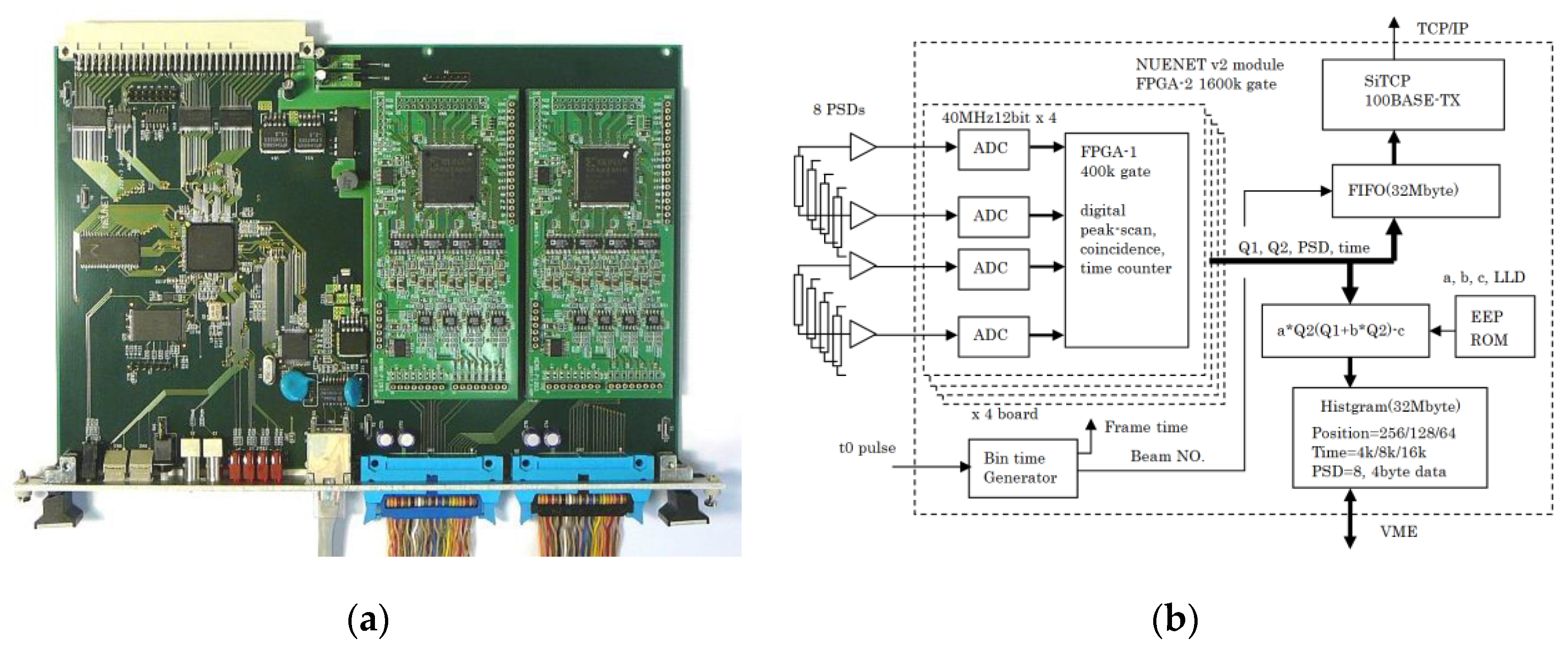
2.1.1. A Neutron Encode with High Speed Network —(NeuNET) Module for 3He Position Sensitive Detector
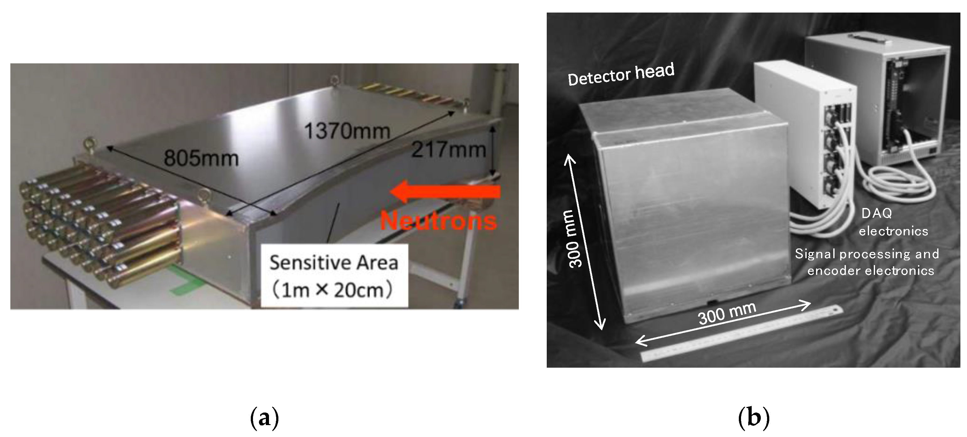
2.1.2. Scintillator Detectors
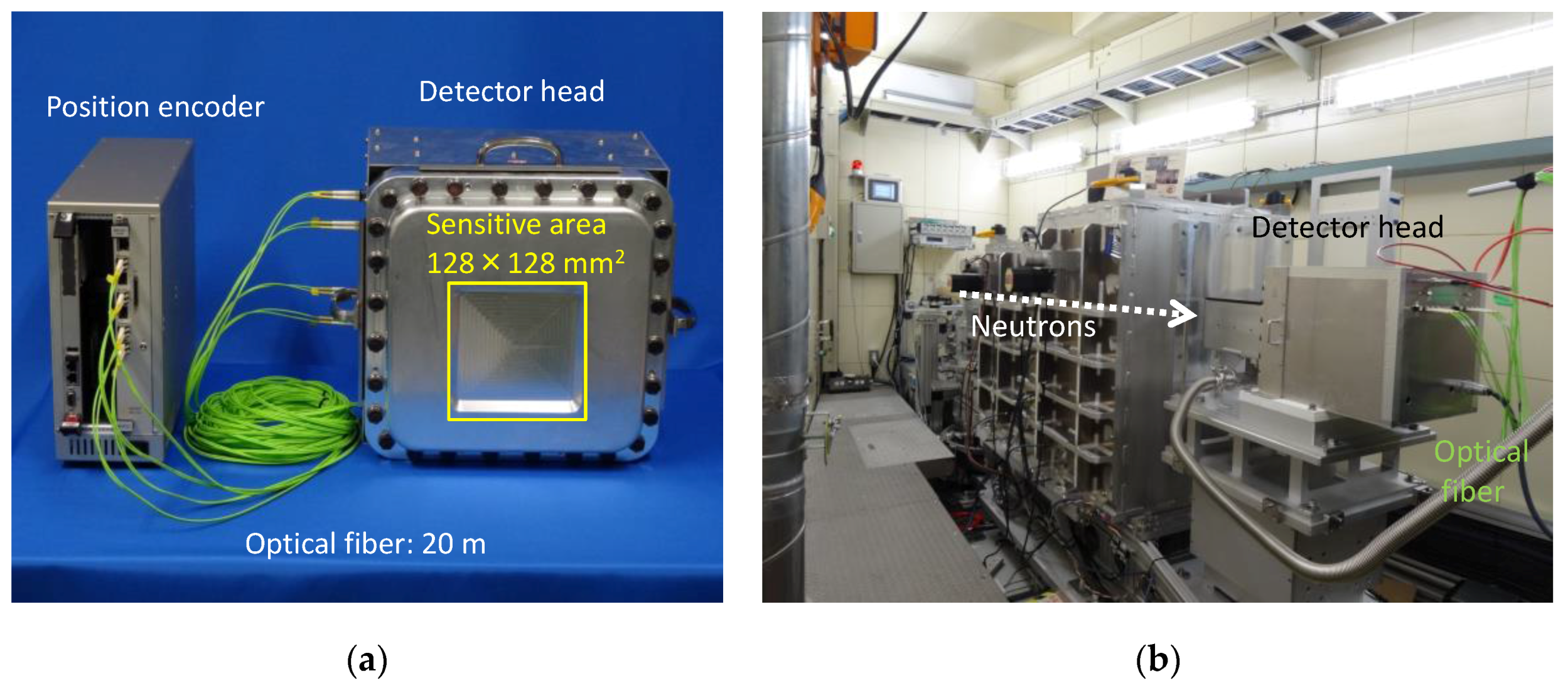
2.1.3. Gas-Based Two-Dimensional Detector
2.2. Supermirror Devices
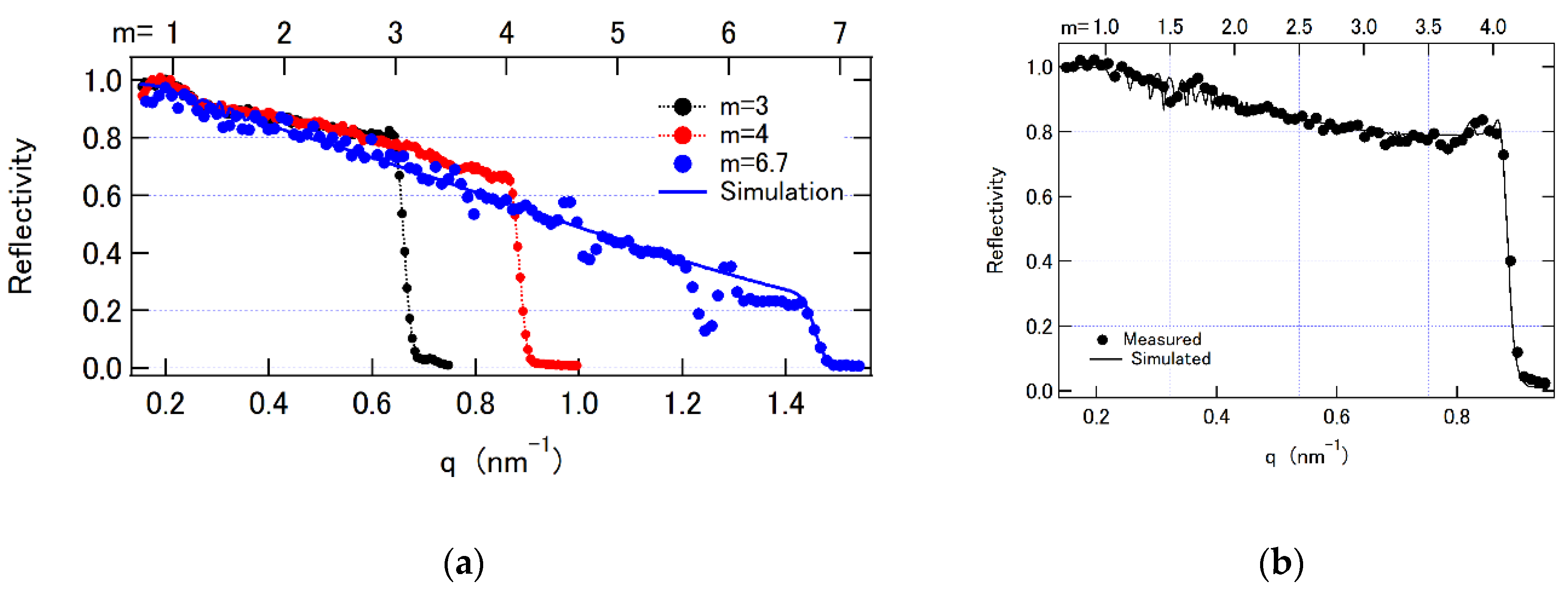
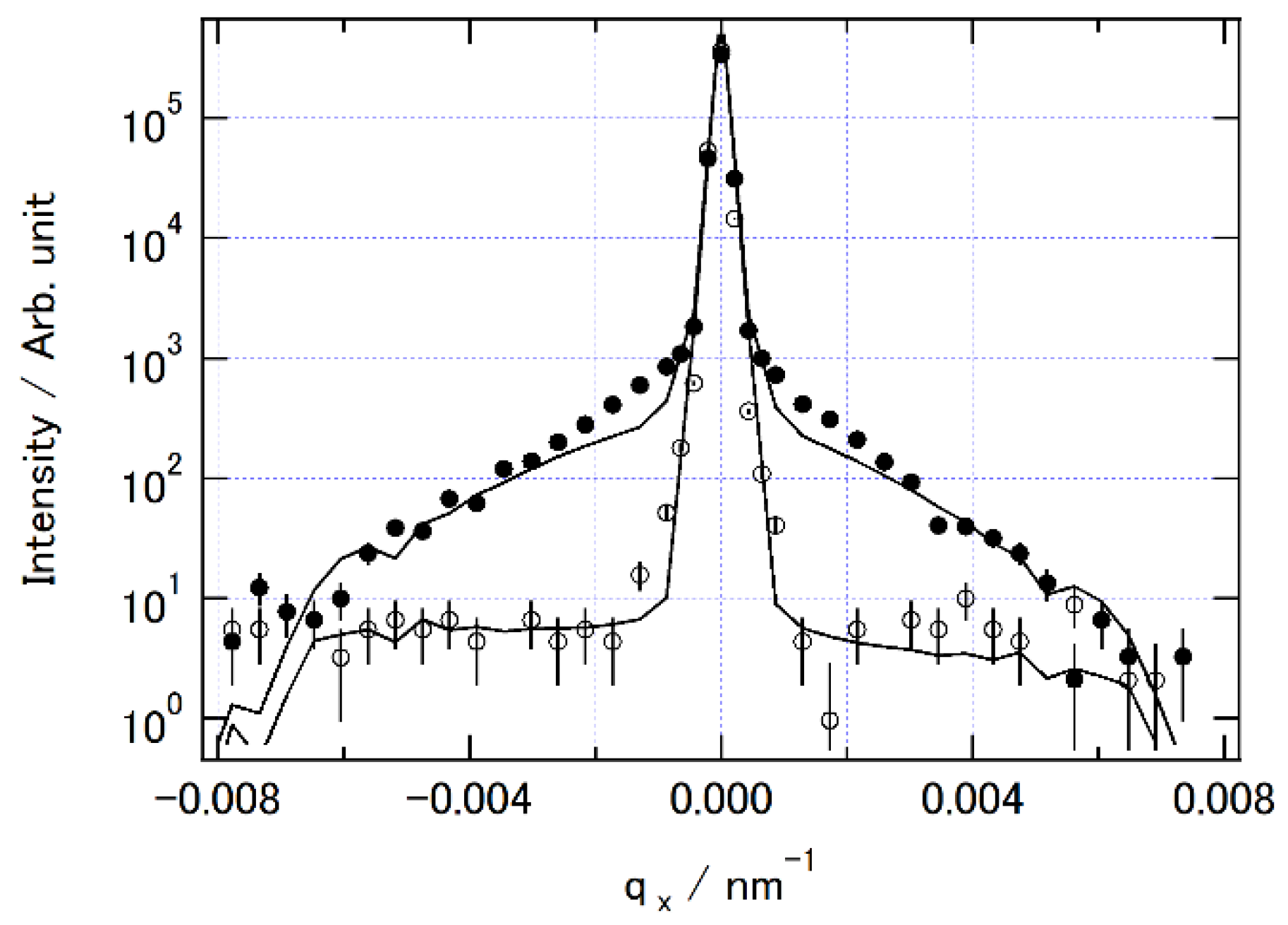
2.2.1. Fabrication and Characterization
Supermirror Coating
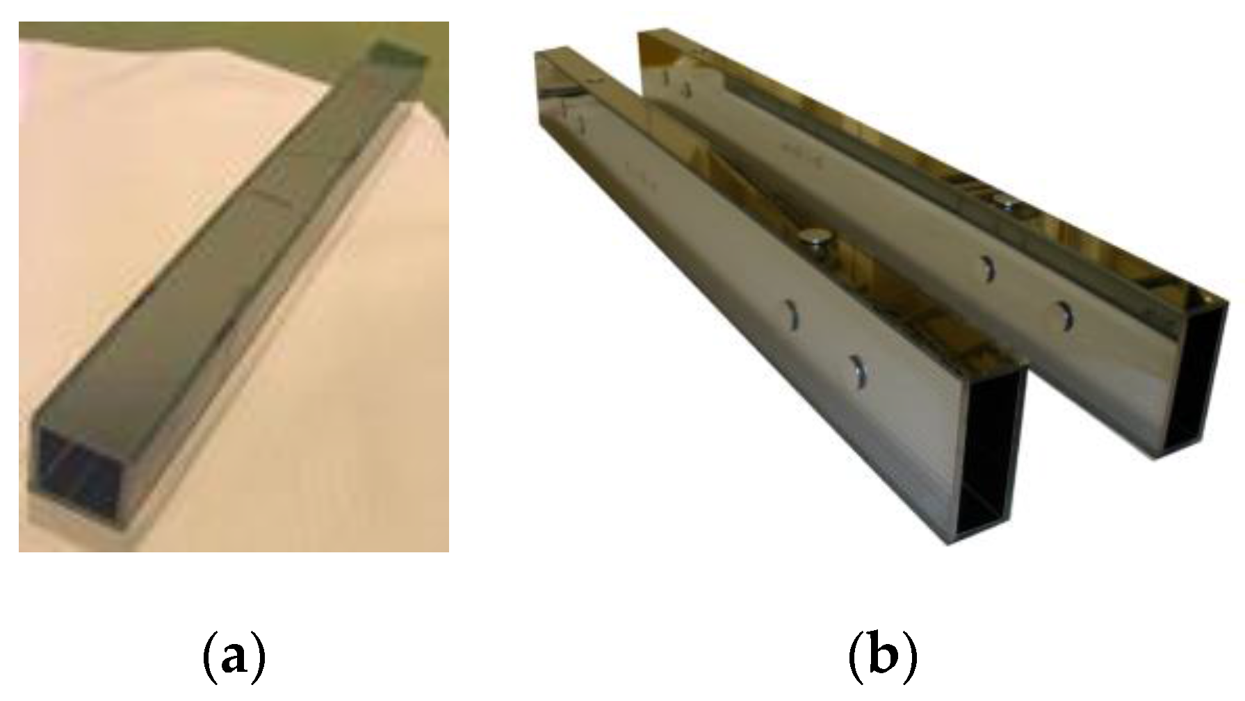
Supermirror Guide
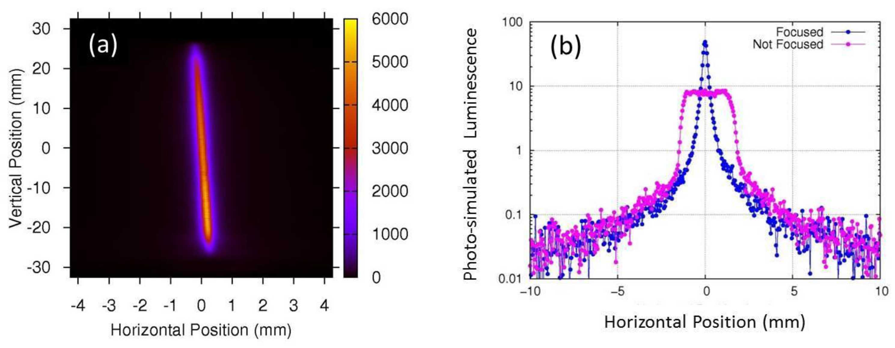
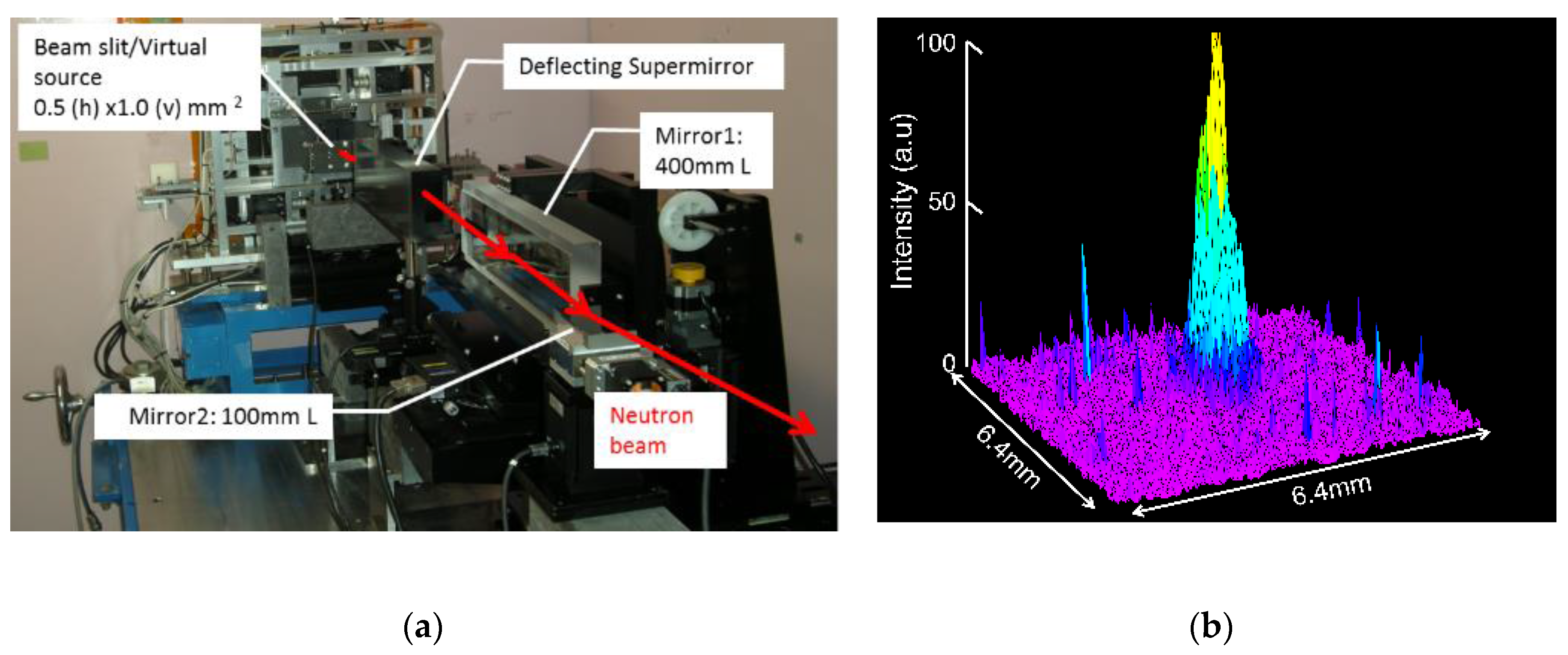
Focusing Mirror
2.3. 3He Neutron Spin Filters
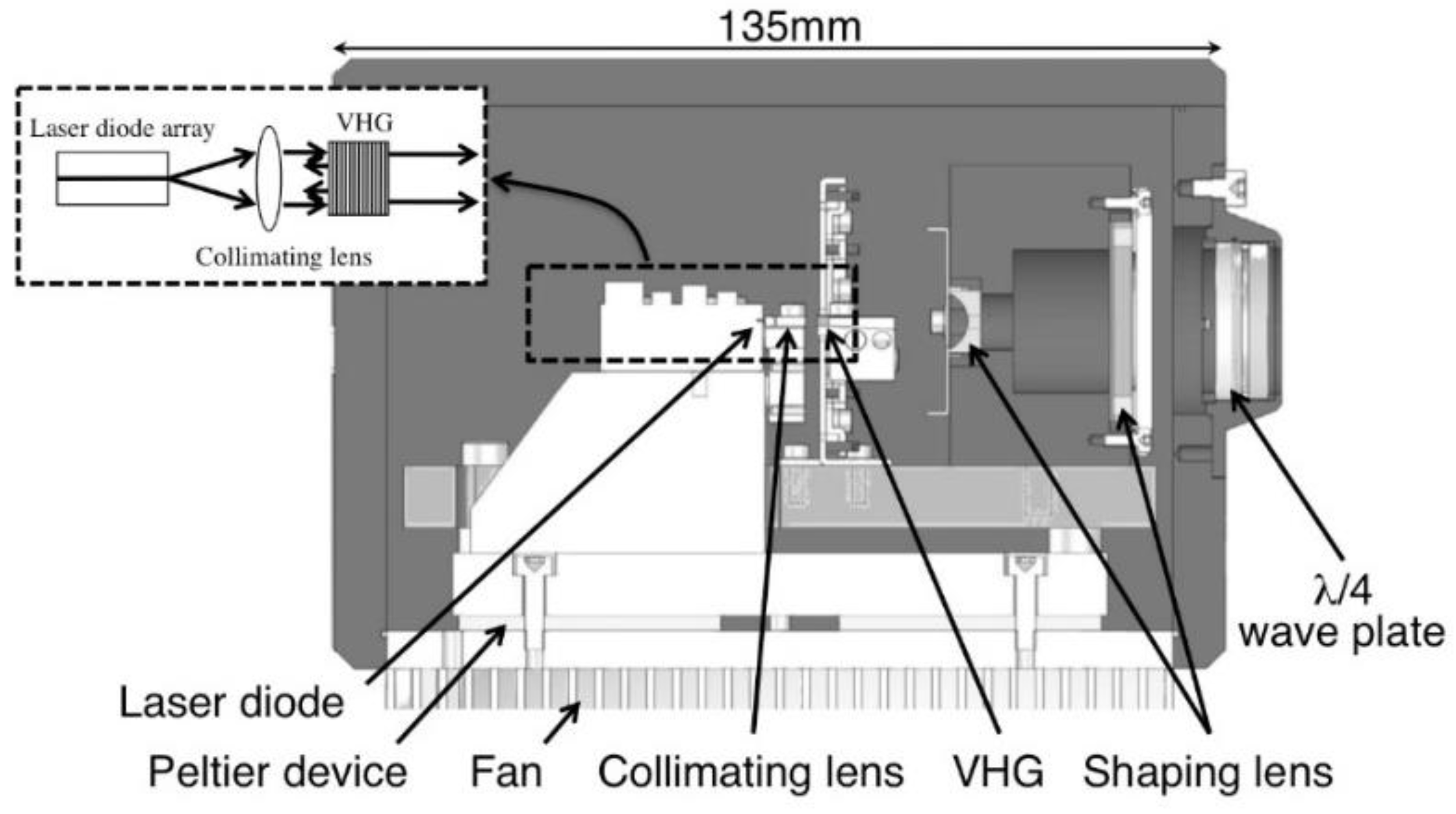
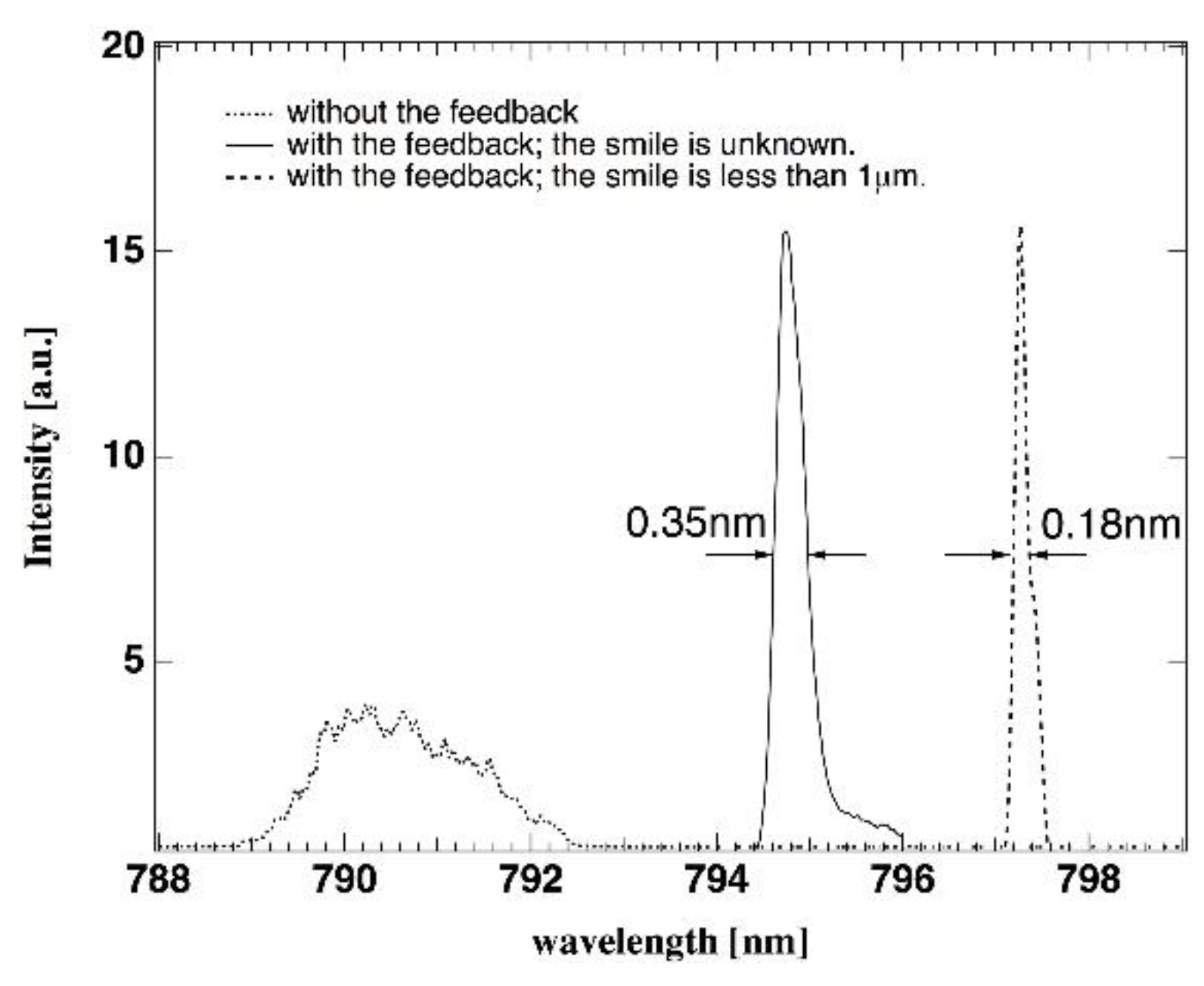
2.3.1. Compact Laser Optics
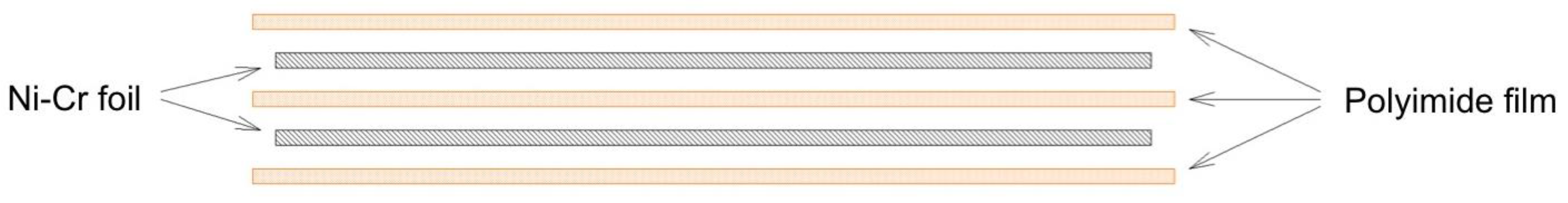
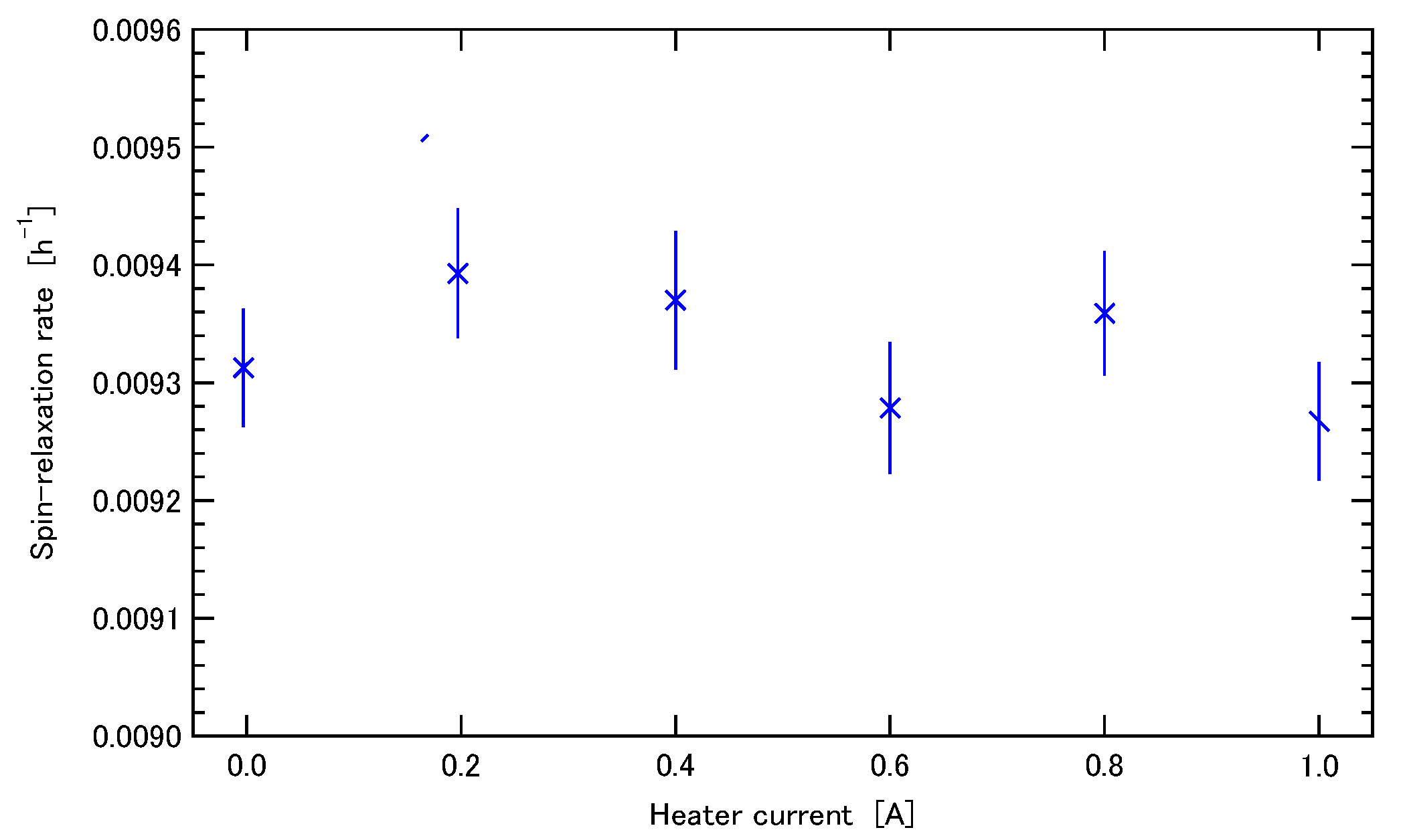
2.3.2. A Non-Magnetic Flexible Heater
2.4. Choppers
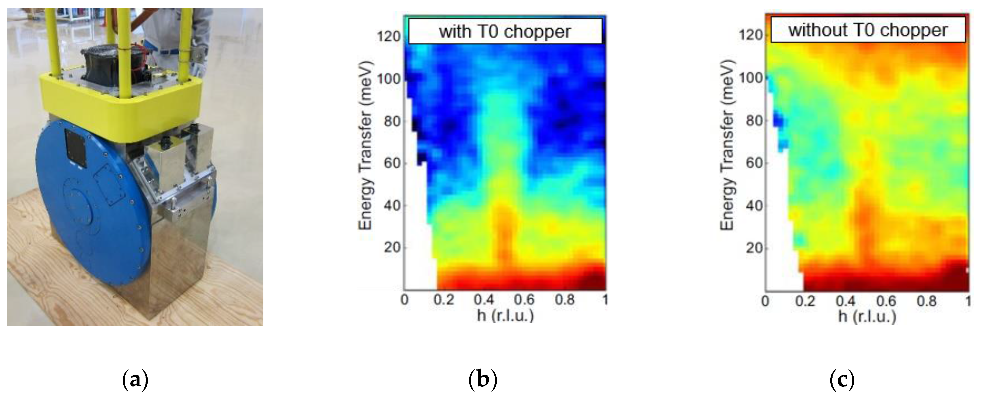
2.4.1. T0 Choppers
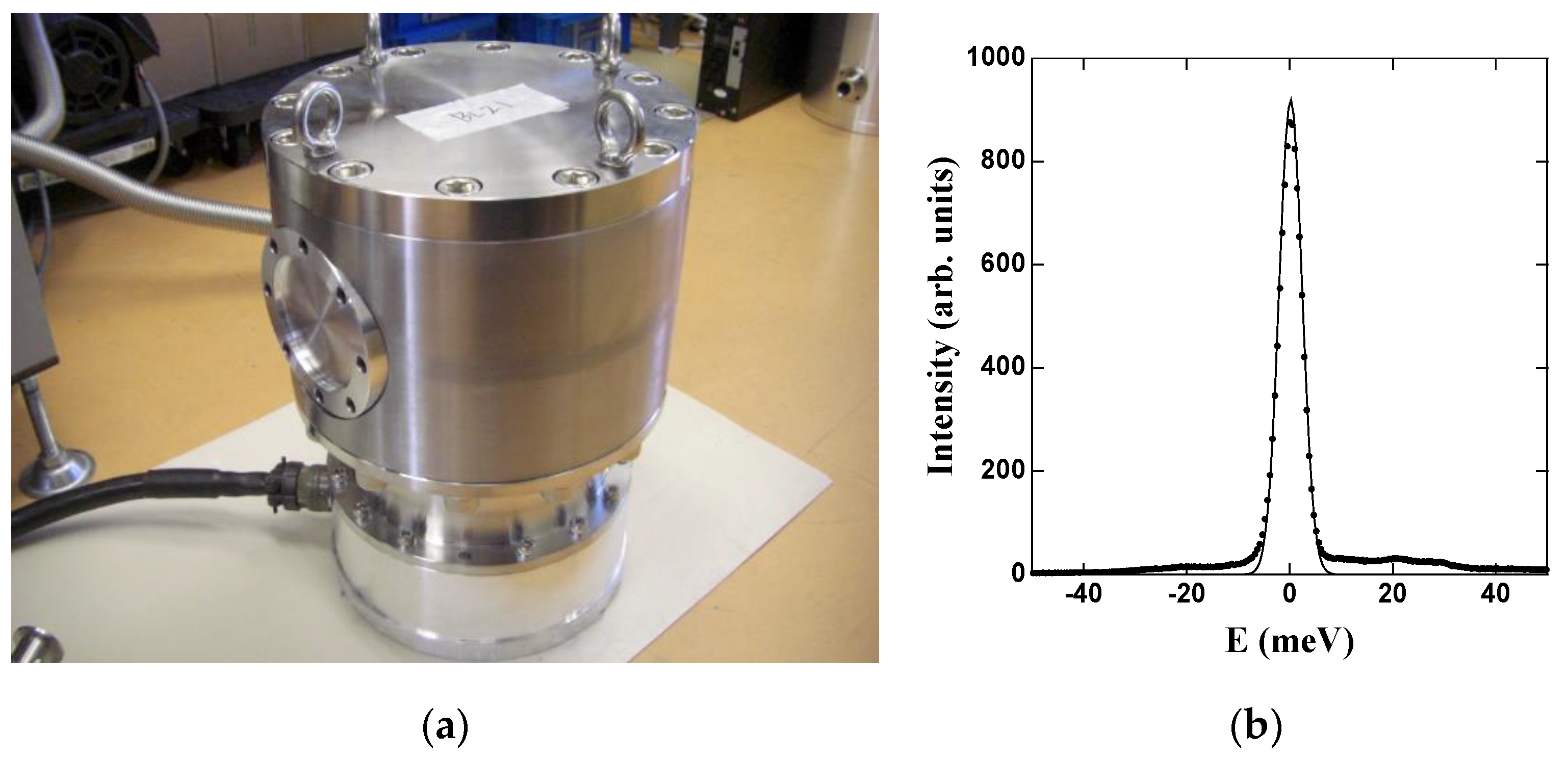
2.4.2. Fermi Choppers
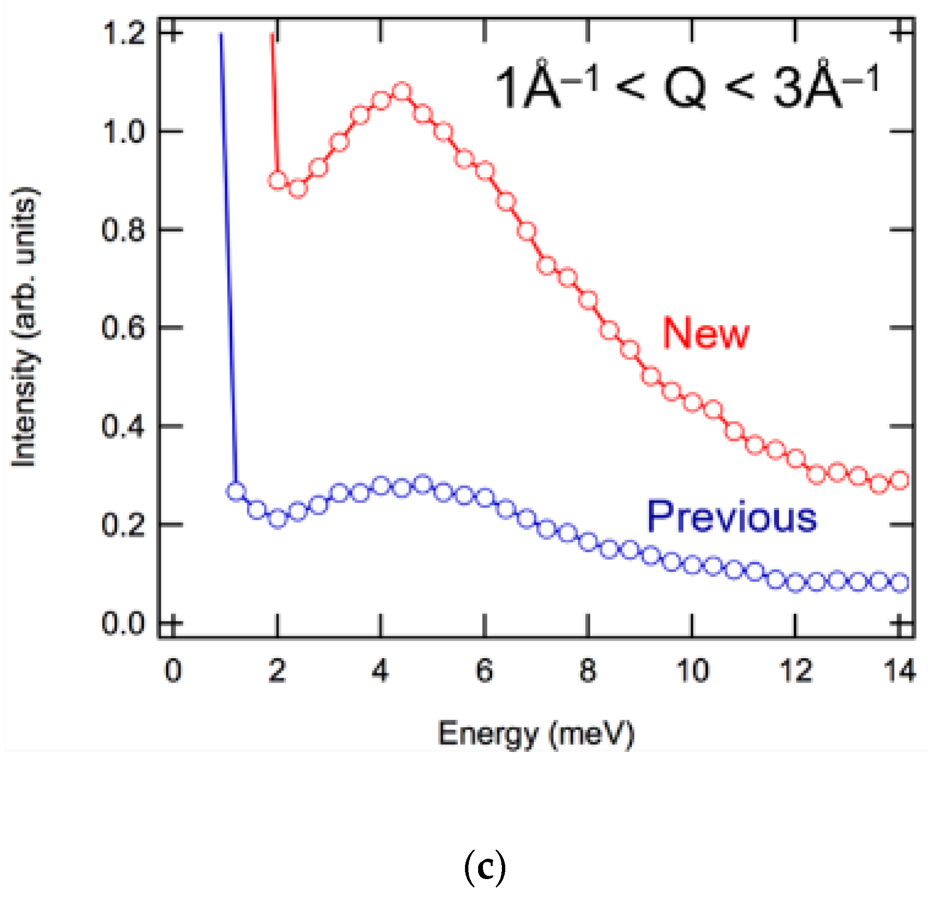
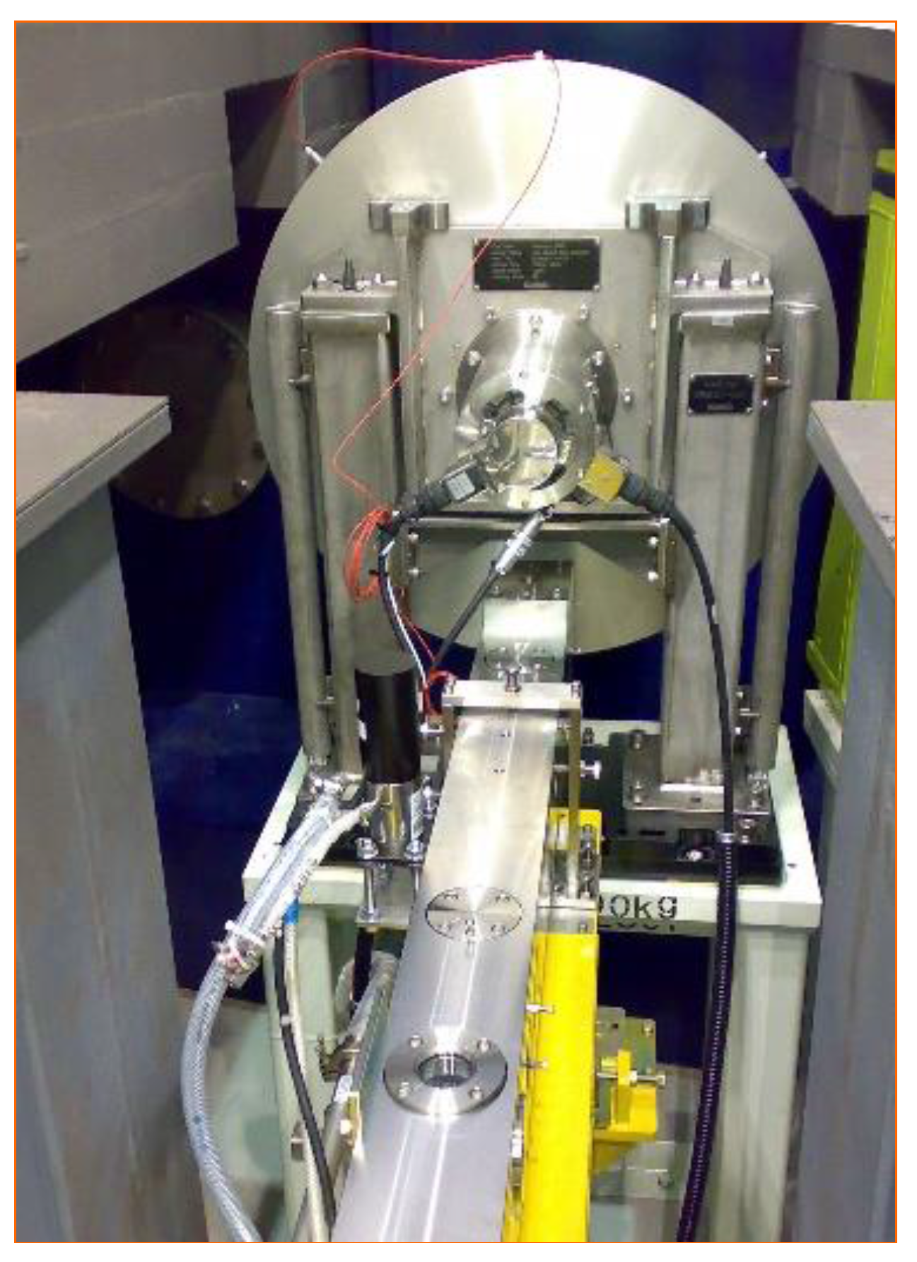
2.4.3. Disk Choppers
Slow Disk-Choppers
- (i)
- For the ease of maintenance, the neutron beam is passed under part of the disk chopper, and the body of chopper disk and motor are mounted on the stand (see Figure 18).
- (ii)
- For the reduction of disk weight, the disk was made of an Al alloy applied with (isotope enriched 10B4C powder + epoxy resin) as a neutron absorber.
- (iii)
- The transmission of neutrons was less than 10−6 at Ei = 100 meV.
Fast Disk-Choppers
3. Computational Environment
3.1. Main Components of MLF Computational Environment
3.1.1. Instrument Control Software Framework: IROHA
Overview of Instrument Control Software
- Scalability: high throughput for large-scale data on the gigabyte order.
- Flexibility: adaptability of various experimental purposes by providing hardware control software for a variety of hardware.
- User-friendly: graphical user interface and controllable via remote access.
- Automation: programing measurement with graphical user interface as well as command-line interface.
IROHA
IROHA2
- Proper role-sharing between the software of individual device control and that of the integrated instrument control.
- The interface with database systems such as MLF experimental database (MLF EXP-DB), the authentication system, the user information database cooperated with the system of J-PARC Users’ office for linking metadata with experimental data.
- Platform-independent user interface.
- Device control server: operation, monitoring and logging outputs of devices. More than 50 devices have been supported.
- Instrument management server: generation of run information, configuration and management of instrument components and user authentication.
- Sequence management server: configuration and management of automatic measurement.
- Integrate control server: integral operation and monitoring of an instrument; monitoring is also available from outside of MLF.
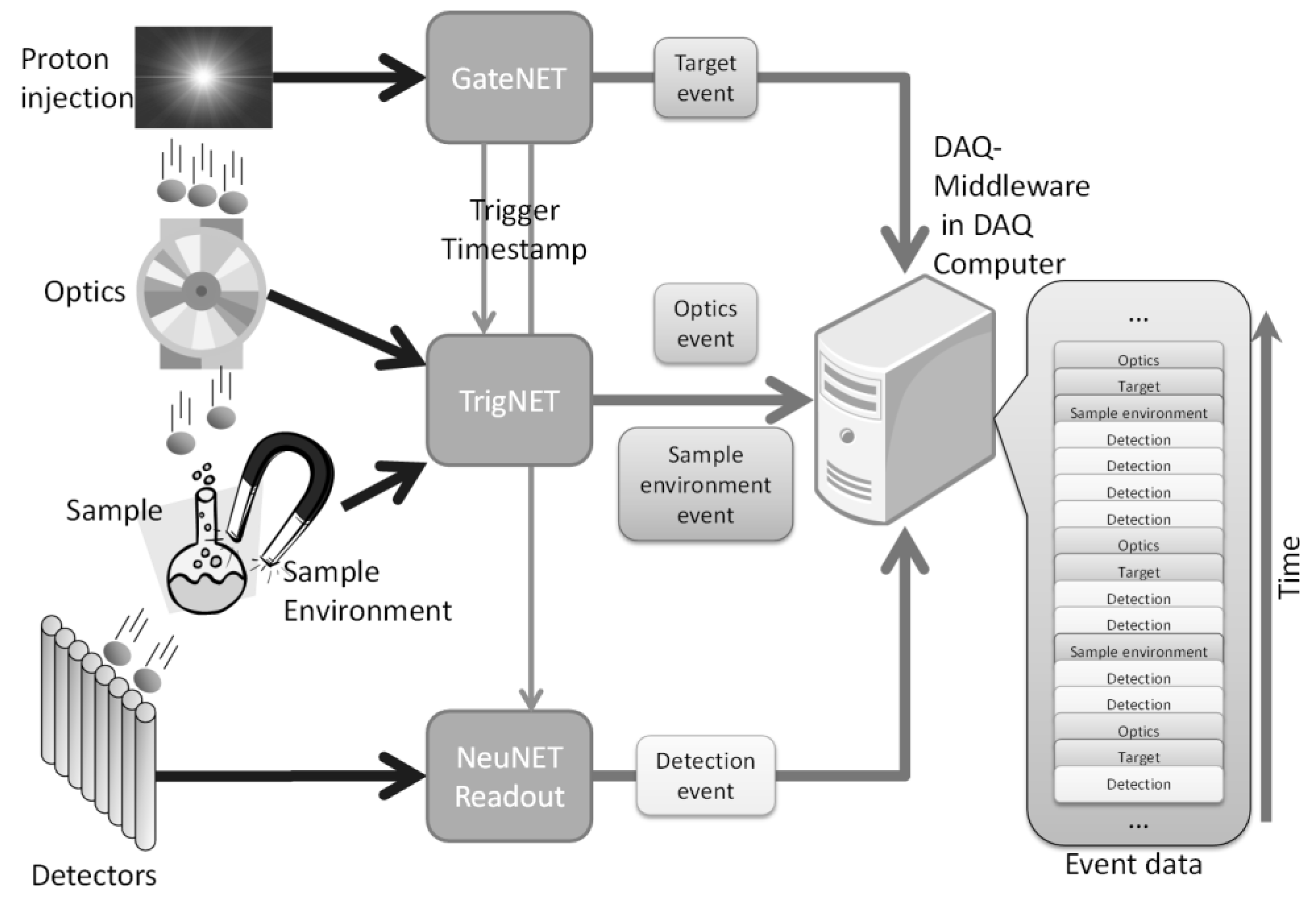
3.1.2. Data Acquisition
Event Recording Method
Data Acquisition Software
3.1.3. Data Reduction and Visualization
Overview
- Data Reduction
- -
- Conversion from the binary raw data, i.e., the event recording data at MLF, to the histograms format.
- -
- Data correction, for example the detector efficiency, the solid angle, the background subtraction, the calculation of absolute value on the structure factor, and so on.
- Data Analysis
- -
- Interpretation of measured data, like structure refinement and simulation calculation.
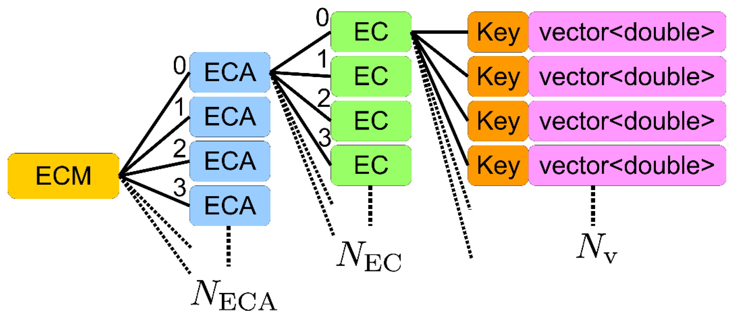
Object-Oriented Data Reduction and Analysis Framework Manyo Library
Standard File Format: NeXus
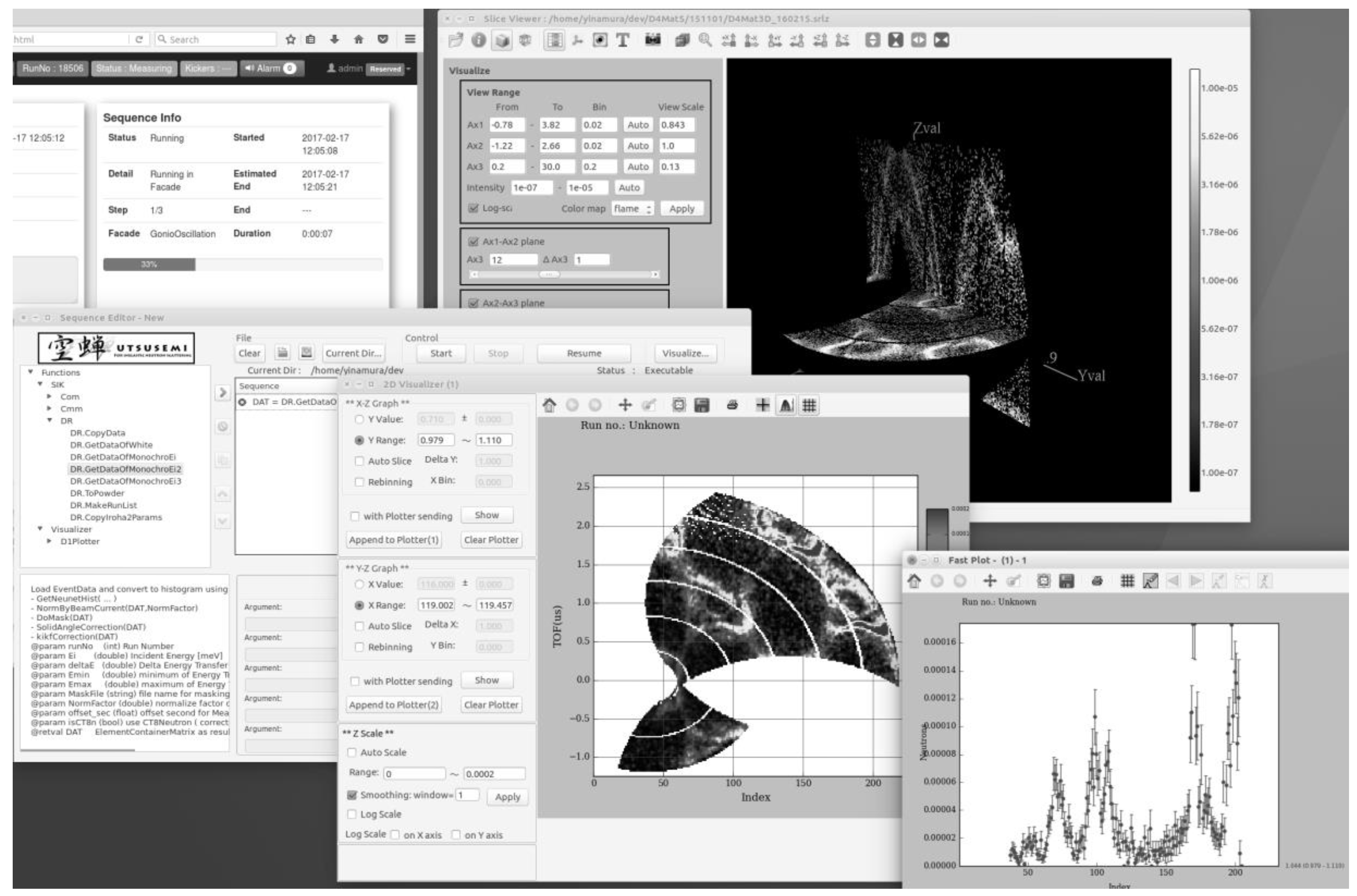
Utsusemi, the Base Software for Data Reduction and Visualization at MLF
3.1.4. Experimental Database: MLF EXP-DB
Overview of Experimental Database
MLF EXP-DB
- Data cataloging: automatically correcting experimental data from instruments and creates the data catalog, which includes information on the paths of data files, samples, measurement conditions, and experimental proposals.
- Central data management: managing data file reposition. It processes the data transfer from instrument local storage to the unified data repository in the facility, archiving for long-term storage and on-demand retrieve.
- Database Link: correcting associated information on experiment such as experimental proposal, primary investigator, and chemical safety of samples by the database link to other business database systems.
- Web portal: providing the interface for data management and data access to facility staff and users via web portals. It is possible to manage, search, and download experimental data in these portals.
Reliability
- High reliability is required for a core system; however, the conventional system runs on a single physical server. By removing the single point of failure, service outages should be avoided as much as possible.
- Scalability for data collection is required to accept the load for data collection increasing with instrument performance and beam intensity. However, the conventional system, which is a single integrated server, does not have such scalability.
- A web portal enabling effective and quick data access should be provided to facility users. A data search function is especially important to find data for analysis from a large amount of data.
- High availability: we improved the system as a redundant distributed system in a switch-over relationship. It is possible to perform a continuous data collection and provide stable data access in this configuration against system failure and service outage.
- Scalability: we redesigned the system to a scaled-out configuration enabling data collection load balancing and partitioning of bloating database. The improved system comprises two physical nodes. This architecture enables us to scale performance by adding nodes responding to the data rate.
- Usability: we improved the web portal for data access by implementing a flexible data search function. Users can search data with various conditions such as experimental proposal, sample, device conditions, etc.
Status of Operation
4. Sample Environment
4.1. SE Equipment Available at MLF
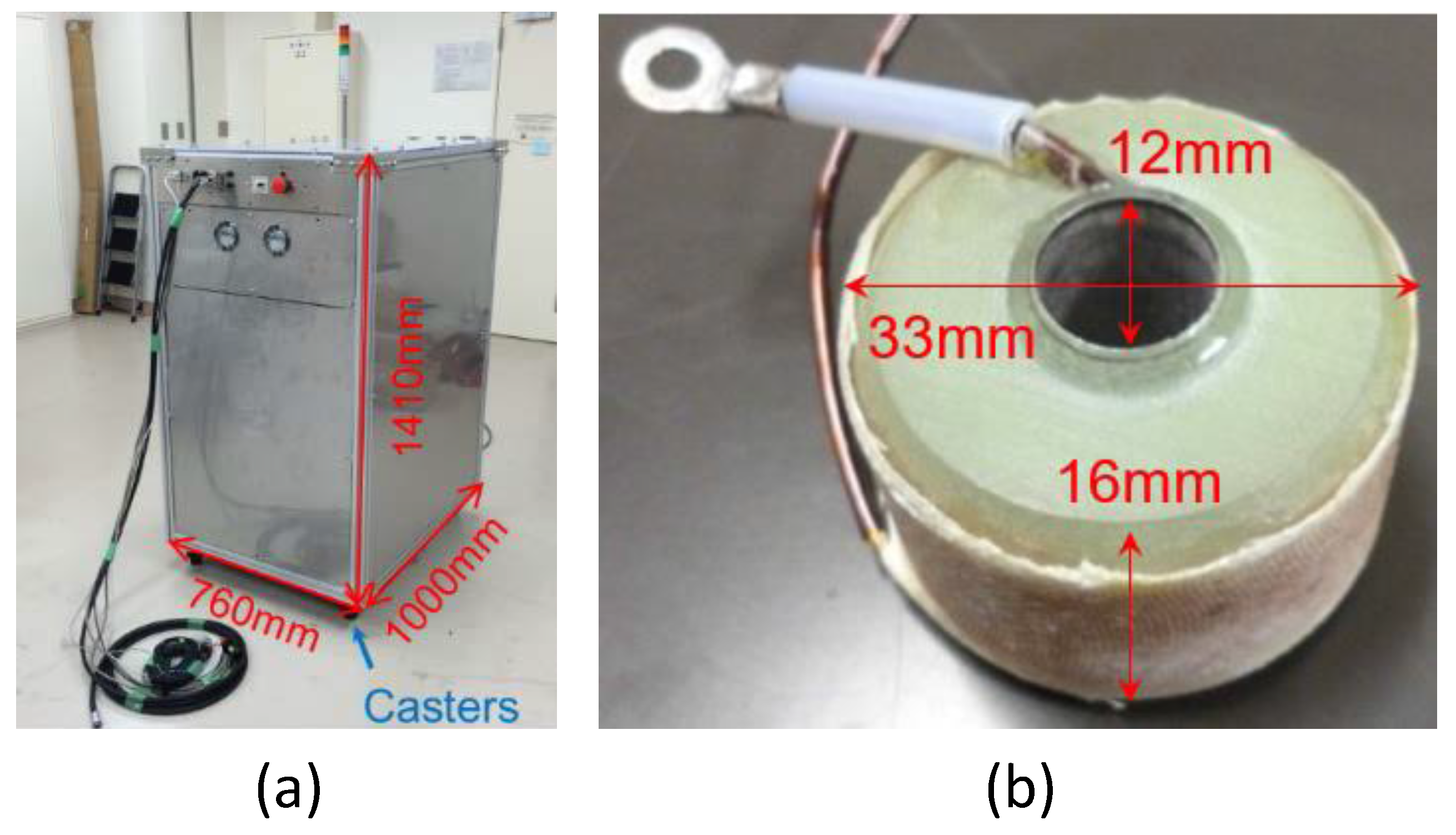
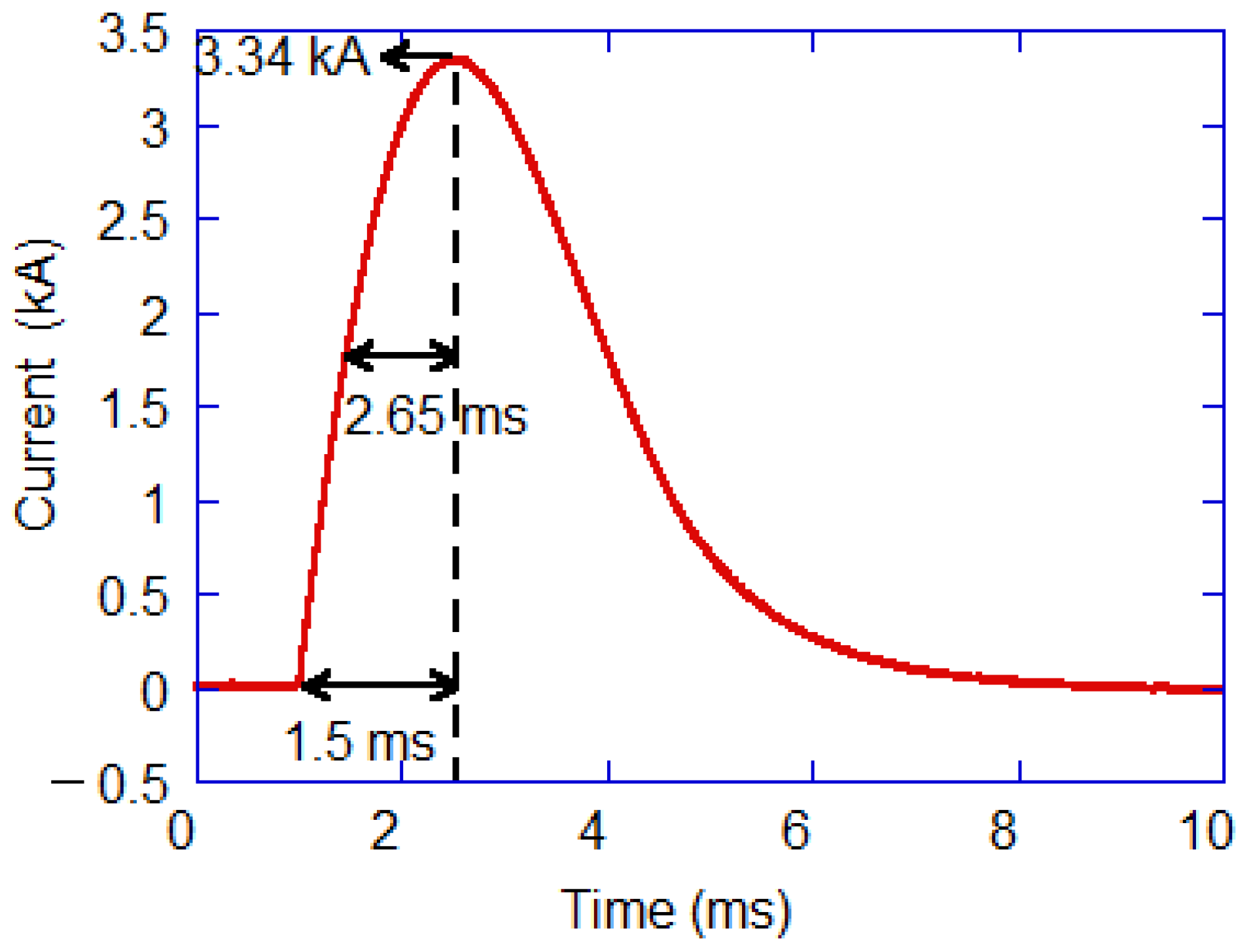
4.2. Development of Pulsed Magnet System
4.2.1. Capacitor Bank Power Supply
4.2.2. Small Solenoid Coil
4.2.3. Cryostat Insert
5. Conclusions
Acknowledgments
Author Contributions
Conflicts of Interest
References
- Satoh, S.; Muto, S.; Kaneko, N.; Uchida, T.; Tanaka, M.; Yasu, Y.; Nakayoshi, K.; Inoue, E.; Sendai, H.; Nakatani, T.; et al. Development of a readout system employing high-speed network for J-PARC. Nucl. Instrum. Methods Phys. Res. A 2008, 600, 103–106. [Google Scholar] [CrossRef]
- Uchida, T.; Tanaka, M. Development of TCP/IP Processing Hardware. In Proceedings of the 2006 IEEE Nuclear Science Symposium Conference Record, San Diego, CA, USA, 29 October–4 November 2006; pp. 1411–1414. [Google Scholar] [CrossRef]
- Sakasai, K.; Nakamura, T.; Katagiri, M.; Soyama, K.; Birumachi, A.; Satoh, S.; Rohdes, N.; Schooneveld, E. Development of neutron detector for engineering materials diffractometer at J-PARC. Nucl. Instrum. Methods Phys. Res. A 2008, 600, 157–160. [Google Scholar] [CrossRef]
- Sakasai, K.; Toh, K.; Nakamura, T.; Harjo, S.; Moriai, A.; Itoh, T.; Abe, J.; Aizawa, K.; Soyama, K.; Katagiri, M.; et al. Development and Installation of Neutron Detectors for Engineering Materials Diffractometer at J-PARC. In Proceedings of the 19th Meeting on International Collaboration of Advanced Neutron Sources (ICANS-XIX), Grindelwald, Switzerland, 8–12 March 2010. [Google Scholar]
- Nakamura, T.; Kawasaki, T.; Hosoya, T.; Toh, K.; Oikawa, K.; Sakasai, K.; Ebine, M.; Birumachi, A.; Soyama, K.; Katagiri, M. A large-area two-dimensional scintillator detector with a wavelength-shifting fibre readout for a time-of-flight single-crystal neutron diffractometer. Nucl. Instrum. Methods Phys. Res. A 2012, 686, 64–70. [Google Scholar] [CrossRef]
- Kawasaki, T.; Nakamura, T.; Hosoya, T.; Oikawa, K.; Ohhara, T.; Kiyanagi, R.; Ebine, M.; Birumachi, A.; Sakasai, K.; Soyama, K.; et al. Detector system of the SENJU single-crystal time-of-flight neutron diffractometer at J-PARC/MLF. Nucl. Instrum. Methods Phys. Res. A 2014, 735, 444–451. [Google Scholar] [CrossRef]
- Toh, K.; Nakamura, T.; Sakasai, K.; Soyama, K.; Hino, M.; Kitaguchi, M.; Yamagishi, H. Development of two-dimensional multiwire-type neutron detector system with individual line readout and optical signal transmission. Nucl. Instrum. Methods Phys. Res. A 2013, 726, 169–174. [Google Scholar] [CrossRef]
- Toh, K.; Nakamura, T.; Sakasai, K.; Soyama, K.; Yamagishi, H. Evaluation of two-dimensional multiwire neutron detector with individual line readout under pulsed neutron irradiation. J. Instrum. 2014, 9, C11019. [Google Scholar] [CrossRef]
- Mezei, F. Novel polarized neutron devices: Supermirror as spin component amplifier. Commun. Phys. 1976, 1, 81–85. [Google Scholar]
- Soyama, K.; Ishiyama, W.; Murakami, K. Enhancement of reflectivity of multilayer neutron mirrors by ion polishing: Optimization of the ion beam parameters. J. Phys. Chem. Solid 1999, 60, 1587–1590. [Google Scholar] [CrossRef]
- Maruyama, R.; Yamazaki, D.; Ebisawa, T.; Hino, M.; Soyama, K. Development of neutron supermirror with large-scale ion-beam sputtering instrument. Physica B 2006, 385–386, 1256–1258. [Google Scholar] [CrossRef]
- Maruyama, R.; Yamazaki, D.; Ebisawa, T.; Hino, M.; Soyama, K. Development of neutron supermirrors with large critical angle. Thin Solid Films 2007, 515, 5704–5706. [Google Scholar] [CrossRef]
- Wood, J. Status of supermirror research at OSMC. Proc. SPIE 1992, 1738, 22–29. [Google Scholar]
- Maruyama, R.; Yamazaki, D.; Ebisawa, T.; Soyama, K. Development of high-reflectivity neutron supermirrors using an ion beam sputtering technique. Nucl. Instrum. Methods Phys. Res. A 2009, 600, 68–70. [Google Scholar] [CrossRef]
- Maruyama, R.; Yamazaki, D.; Ebisawa, T.; Soyama, K. Effect of interfacial roughness correlation on diffuse scattering intensity in a neutron supermirror. J. Appl. Phys. 2009, 105, 083527. [Google Scholar] [CrossRef]
- Kajimoto, R.; Nakajima, K.; Nakamura, M.; Soyama, K.; Yokoo, T.; Oikawa, K.; Arai, M. Study of the neutron guide design of the 4SEASONS spectrometer at J-PARC. Nucl. Instrum. Methods Phys. Res. A 2009, 600, 185–188. [Google Scholar] [CrossRef]
- Nakajima, K.; Ohira-Kawamura, S.; Kikuchi, T.; Nakamura, M.; Kajimoto, R.; Inamura, Y.; Takahashi, N.; Aizawa, K.; Suzuya, K.; Shibata, K.; et al. AMATERAS: A Cold-Neutron Disk Chopper Spectrometer. J. Phys. Soc. Jpn. 2011, 80, SB028. [Google Scholar] [CrossRef]
- Yamamura, K. Fabrication of Ultra Precision Optics by Numerically Controlled Local Wet Etching. Ann. CIRP 2007, 56, 541–544. [Google Scholar] [CrossRef]
- Yamazaki, D.; Maruyama, R.; Soyama, K.; Takai, H.; Nagano, M.; Yamamura, K. Neutron beam focusing using large-m supermirrors coated on precisely-figured aspheric surfaces. J. Phys. Conf. Ser. 2010, 251, 012076. [Google Scholar] [CrossRef]
- Yamazaki, D.; Nagano, M.; Maruyama, R.; Hayashida, H.; Soyama, K.; Yamamura, K. Neutron Focusing by a Kirkpatrick-Baez Type Super-mirror. JPS Conf. Proc. 2015, 8, 051009. [Google Scholar] [CrossRef]
- Chupp, T.E.; Wagshul, M.E.; Coulter, K.P.; McDonald, A.B.; Happer, W. Polarized, high-density, gaseous 3He targets. Phys. Rev. C 1987, 36, 2244–2251. [Google Scholar] [CrossRef]
- Rich, D.R.; Gentile, T.R.; Smith, T.B.; Thompson, A.K. Spin exchange optical pumping at pressures near 1 bar for neutron spin filters. Appl. Phys. Lett. 2002, 80, 2210–2212. [Google Scholar] [CrossRef]
- Moser, C.; Lawrence Ho, L.; Havermeyer, F. Self-aligned non-dispersive external cavity tunable laser. Opt. Express 2008, 16, 16691–16696. [Google Scholar] [CrossRef] [PubMed]
- Liu, X.; Zhao, W.; Liu, H. Thermal Stress in High Power Semiconductor Lasers. In Packaging of High Power Semiconductor Lasers, 1st ed.; Springer: New York, NY, USA, 2015; pp. 89–105. ISBN 978-1-4939-5590-9. [Google Scholar]
- Kissel, H.; Köhler, B.; Biesenbach, J. High-power diode laser pumps for alkali lasers (DPALs). Proc. SPIE 2012, 824, 82410Q. [Google Scholar] [CrossRef]
- Hayashida, H.; Oku, T.; Kira, H.; Sakai, K.; Takeda, M.; Sakaguchi, Y.; Ino, T.; Shinohara, T.; Ohoyama, K.; Suzuki, J.; et al. Development and demonstration of in-situ SEOP 3He spin filter system for neutron spin analyzer on the SHARAKU polarized neutron reflectometer at J-PARC. J. Phys. Conf. Ser. 2014, 528, 012020. [Google Scholar] [CrossRef]
- Kira, H.; Hayashida, H.; Iwase, H.; Ohishi, K.; Suzuki, J.; Oku, T.; Sakai, K.; Hiroi, K.; Takata, S.; Ino, T.; et al. Demonstration Study of Small-Angle Polarized Neutron Scattering Using Polarized 3He Neutron Spin Filter. JPS Conf. Proc. 2015, 8, 036008. [Google Scholar] [CrossRef]
- Walker, T.G. Fundamentals of Spin-Exchange Optical Pumping. J. Phys. Conf. Ser. 2011, 294, 012001. [Google Scholar] [CrossRef]
- Babcock, E.; Nelson, I.; Kadlecek, S.; Driehuys, B.; Anderson, L.W.; Hersman, F.W.; Walker, T.G. Hybrid Spin-Exchange Optical Pumping of 3He. Phys. Rev. Lett. 2003, 91, 123003. [Google Scholar] [CrossRef] [PubMed]
- Tong, X.; Pierce, J.; Lee, W.T.; Fleenor, M.; Chen, W.C.; Jones, G.L.; Robertson, J.L. Electrical heating for SEOP-based polarized 3He system. J. Phys. Conf. Ser. 2010, 251, 012087. [Google Scholar] [CrossRef]
- Babcock, E.; Salhi, Z.; Theisselmann, T.; Starostin, D.; Schmeissner, J.; Feoktystov, A.; Mattauch, S.; Pistel, P.; Radulescu, A.; Ioffe, A. SEOP polarized 3He Neutron Spin Filters for the JCNS user program. J. Phys. Conf. Ser. 2016, 711, 012008. [Google Scholar] [CrossRef]
- Ino, T.; Hayashida, H.; Kira, H.; Oku, T.; Sakai, K. Non-magnetic flexible heaters for spin-exchange optical pumping of 3He and other applications. Rev. Sci. Instrum. 2016, 87, 115108. [Google Scholar] [CrossRef] [PubMed]
- Itoh, S.; Ueno, K.; Ohkubo, R.; Sagehashi, H.; Funahashi, Y.; Yokoo, T. T0 chopper developed at KEK. Nucl. Instr. Methods Phys. Res. Sect. A 2012, 661, 86–92. [Google Scholar] [CrossRef]
- Kajimoto, R.; Nakamura, M.; Inamura, Y.; Mizuno, F.; Nakajima, K.; Takahashi, N.; Ohira-Kawamura, S.; Yokoo, T.; Maruyama, R.; Soyama, K.; et al. Commissioning of the Fermi-Chopper Spectrometer 4SEASONS at J-PARC—Background Study. In Proceedings of the 19th Meeting on International Collaboration of Advanced Neutron Sources (ICANS-XIX), Grindelwald, Switzerland, 8–12 March 2010. [Google Scholar]
- Kajimoto, R.; Nakamura, M.; Inamura, Y.; Mizuno, F.; Nakajima, K.; Ohira-Kawamura, S.; Yokoo, T.; Nakatani, T.; Maruyama, R.; Soyama, K.; et al. The Fermi Chopper Spectrometer 4SEASONS at J-PARC. J. Phys. Soc. Jpn. 2011, 80, SB025. [Google Scholar] [CrossRef]
- Fermi, E.; Marshall, J.; Marshall, L. A Thermal Neutron Velocity Selector and Its Application to the Measurement of the Cross Section of Boron. Phys. Rev. 1947, 72, 193–196. [Google Scholar] [CrossRef]
- Itoh, S.; Ueno, K.; Yokoo, T. Fermi chopper developed at KEK. Nucl. Instrum. Methods Phys. Res. A 2012, 661, 58–63. [Google Scholar] [CrossRef]
- Nakamura, M.; Nakajima, K.; Kajimoto, R.; Arai, M. Utilization of multiple incident energies on Cold-Neutron Disk-Chopper Spectrometer at J-PARC. J. Neutron Res. 2007, 15, 31–37. [Google Scholar] [CrossRef]
- Nakamura, M.; Kajimoto, R.; Inamura, Y.; Mizuno, F.; Fujita, M.; Yokoo, T.; Arai, M. First Demonstration of Novel Method for Inelastic Neutron Scattering Measurement Utilizing Multiple Incident Energies. J. Phys. Soc. Jpn. 2009, 78, 093002. [Google Scholar] [CrossRef]
- Nakamura, M.; Kajimoto, R. General Formulae for the Optimized Design of Fermi Chopper Spectrometer. JPS Conf. Proc. 2014, 1, 014018. [Google Scholar] [CrossRef]
- Suzuki, J.; Murakami, K.; Manabe, A.; Kawabata, S.; Otomo, T.; Furusaka, M. Object-oriented data analysis environment for neutron scattering. Nucl. Instrum. Methods Phys. Res. A 2004, 534, 175–179. [Google Scholar] [CrossRef]
- Yasu, Y.; Nakayoshi, K.; Sendai, H.; Inoue, E.; Tanaka, M.; Suzuki, S.; Satoh, S.; Muto, S.; Otomo, T.; Nakatani, T.; et al. Development of DAQ-Middleware. In Proceedings of the 17th International Conference on Computing in High Energy and Nuclear Physics (CHEP09), Prague, Czech Republic, 21–27 March 2009; p. 022025. [Google Scholar] [CrossRef]
- Mcgreevy, R.; Otomo, T.; Anderson, I.; Miller, S.; Geist, A. New opportunities for data analysis software: An international Collaboration. Neutron News 2004, 15, 25–27. [Google Scholar] [CrossRef]
- Nakatani, T.; Inamura, Y.; Ito, T.; Harjo, S.; Kajimoto, R.; Arai, M.; Ohhara, T.; Nakagawa, H.; Aoyagi, T.; Otomo, T.; et al. The Implementation of the Software Framework in J-PARC/MLF. In Proceedings of the 12th International Conference on Accelerator and Large Experimental Physics Control Systems, Kobe, Japan, 12–16 October 2009; p. 673. [Google Scholar]
- Nakatani, T.; Inamura, Y.; Ito, T.; Otomo, T. Data acquisition and device control software framework in MLF, J-PARC. In Proceedings of the 21st Meeting of the International Collaboration on Advanced Neutron Sources (ICANS-XXI), Mito, Japan, 29 September–3 October 2014; p. 493. [Google Scholar] [CrossRef]
- Nakatani, T.; Inamura, Y.; Ito, T.; Otomo, T. The Control Software Framework of the Web Base. In Proceedings of the 2nd International Symposium on Science at J-PARC, Tsukuba, Japan, 12–15 July 2014; p. 036013. [Google Scholar] [CrossRef]
- Nakatani, T.; Inamura, Y.; Ito, T.; Moriyama, K. IROHA2: Standard instrument control software framework in MLF, J-PARC. In Proceedings of the New Opportunities for Better User Group Software NOBUGS2016, Copenhagen, Denmark, 17–19 October 2016; p. 76. [Google Scholar] [CrossRef]
- Nakatani, T.; Inamura, Y.; Ito, T.; Otomo, T.; Satoh, S.; Muto, S.; Nakayoshi, K.; Sendai, H.; Inoue, E.; Yasu, Y. Event Mode Data Acquisition System at MLF/J-PARC. In Proceedings of the 19th Meeting on International Collaboration of Advanced Neutron Sources (ICANS-XIX), Grindelwald, Switzerland, 8–12 March 2010. [Google Scholar]
- Nakatani, T.; Inamura, Y.; Moriyama, K.; Ito, T.; Muto, S.; Otomo, T. Event recording data acquisition system and experiment data management system for neutron experiments at MLF, J-PARC. In Proceedings of the 12th Asia Pacific Physics Conference (APPC12), Chiba, Japan, 14–19 July 2013; p. 014010. [Google Scholar] [CrossRef]
- Uchida, T. Hardware-Based TCP Processor for Gigabit Ethernet. IEEE Trans. Nucl. Sci. 2008, 55, 1631–1637. [Google Scholar] [CrossRef]
- Nakayoshi, K.; Yasu, Y.; Inoue, E.; Sendai, H.; Tanaka, M.; Satoh, S.; Muto, S.; Kaneko, N.; Otomo, T.; Nakatani, T.; et al. Development of a Data Acquisition Sub-System using DAQ-Middleware. Nucl. Instrum. Methods Phys. Res. A 2009, 600, 173–175. [Google Scholar] [CrossRef]
- Nakayoshi, K.; Yasu, Y.; Inoue, E.; Sendai, H.; Tanaka, M.; Satoh, S.; Muto, S.; Suzuki, J.; Otomo, T.; Nakatani, T.; et al. DAQ-Middleware for MLF/J-PARC. Nucl. Instrum. Methods Phys. Res. A 2010, 623, 537–539. [Google Scholar] [CrossRef]
- Yasu, Y.; Nakayoshi, K.; Sendai, H.; Inoue, E. Functionally of DAQ-Middleware. IEEE Trans. Nucl. Sci. 2010, 57, 487–490. [Google Scholar] [CrossRef]
- Suzuki, J.; Nakatani, T.; Ohhara, T.; Inamura, Y.; Yonemura, M.; Morishima, T.; Aoyagi, T.; Manabe, A.; Otomo, T. Object-oriented data analysis framework for neutron scattering experiments. Nucl. Instrum. Methods Phys. Res. A 2009, 600, 123–125. [Google Scholar] [CrossRef]
- Suzuki, J.; Inamura, Y.; Ito, T.; Nakatani, T.; Otomo, T. “Manyo-Lib” Object-Oriented Data Analysis Framework for Neutron Scattering. In Proceedings of the New Opportunities for Better User Group Software NOBUGS2016, Copenhagen, Denmark, 17–19 October 2016; p. 72. [Google Scholar]
- Inamura, Y.; Nakatani, T.; Suzuki, J.; Otomo, T. Development status of software ‘Utsusemi’ for Chopper Spectrometers at MLF, J-PARC. J. Phys. Soc. Jpn. 2013, 82, SA031. [Google Scholar] [CrossRef]
- Harjo, S.; Ito, T.; Aizawa, K.; Arima, H.; Abe, J.; Moriai, A.; Iwahashi, T.; Kamiyama, K. Current Status of Engineering Materials Diffractometer at J-PARC. Mater. Sci. Forum 2011, 681, 443–448. [Google Scholar] [CrossRef]
- Kawasaki, T.; Ito, T.; Inamura, Y.; Nakatani, T.; Harjo, S.; Gong, W.; Iwahashi, T.; Aizawa, K. Neutron Diffraction Study of Piezoelectric Material under Cyclic Electric Field using Event Recording Technique. In Proceedings of the 21st Meeting of the International Collaboration on Advanced Neutron Sources (ICANS-XXI), Mito, Japan, 29 September–3 October 2014; pp. 528–531. [Google Scholar] [CrossRef]
- Moriyama, K.; Nakatani, T. A Data Management Infrastructure for Neutron Scattering Experiments in J-PARC/MLF. In Proceedings of the 15th International Conference on Accelerator and Large Experimental Physics Control Systems ICALEPCS2015, Melbourne, Australia, 17–23 October 2015; p. 834. [Google Scholar]
- Moriyama, K.; Nakatani, T. Recent Progress in the Development of MLF EXP-DB in J-PARC. In Proceedings of the New Opportunities for Better User Group Software NOBUGS2016, Copenhagen, Denmark, 17–19 October 2016; p. 80. [Google Scholar] [CrossRef]
- Aso, T.; Yamauchi, Y.; Sakaguchi, Y.; Munakata, K.; Ishikado, M.; Ohira-Kawamura, S.; Yokoo, T.; Watanabe, M.; Takata, S.; Hattori, T.; et al. Present status of sample environment at J-PARC MLF. In Proceedings of the 21th International Collaboration on Advanced Neutron Source (ICANS-XXI), Mito, Japan, 29 September–3 October 2014. [Google Scholar]
- Ohira-Kawamura, S.; Oku, T.; Watanabe, M.; Takahashi, R.; Munakata, K.; Sakaguchi, Y.; Ishikado, M.; Ohuchi, K.; Hattori, T.; Kira, H.; et al. Sample Environment at the J-PARC MLF. J. Neutron Res. 2017, 19, 15–22. [Google Scholar] [CrossRef]
- J-PARC. Available online: http://j-parc.jp/researcher/MatLife/en/se/equipment.html (accessed on 27 July 2017).
- Steiner, M.; Tennant, D.A.; Smeibidl, P. New high field magnet for neutron scattering at Hahn-Meitner Institute. J. Phys. Conf. Ser. 2006, 51, 470–474. [Google Scholar] [CrossRef] [Green Version]
- Smeibidl, P.; Tennant, A.; Ehmler, H.; Bird, M. Neutron Scattering at Highest Magnetic Fields at the Helmholtz Centre Berlin. J. Low Temp. Phys. 2010, 159, 402–405. [Google Scholar] [CrossRef]
- Nojiri, H.; Takahashi, K.; Fukuda, T.; Fujita, M.; Arai, M.; Motokawa, M. 25T repeating pulsed magnetic fields system for neutron diffraction experiments. Physica B 1998, 241–243, 210–212. [Google Scholar]
- Nojiri, M.; Motokawa, H.; Takahashi, K.; Arai, M. 30 T repeating pulsed field system for neutron diffraction. IEEE Trans. Appl. Supercond. 2000, 10, 534–537. [Google Scholar] [CrossRef]
- Watanabe, M.; Nojiri, H.; Itoh, S.; Ohira-Kawamura, S.; Kihara, T.; Masuda, T.; Sahara, T.; Soda, M.; Takahashi, R. Development of compact high field pulsed magnet system for new sample environment equipment at MLF in J-PARC. In Proceedings of the International Symposium of Quantum Beam Science at Ibaraki University, Mito, Japan, 18–20 November 2016. [Google Scholar]


| Beam Line | Type of Chopper (No.) | Manufacturers |
|---|---|---|
| BL01 | SI(2) | KOBELCO |
| BL02 | FII(1), FI(2), SII(2), SI(1) | KOBELCO |
| BL03 | SI(1) | MEISYO |
| BL04 | SII(1) | MEISYO |
| BL05 | none | - |
| BL06 | SI(2) | Vacuum Products. |
| BL08 | SII(1), SI(2) | MEISYO |
| BL09 | SI(3) | MEISYO |
| BL10 | SI(1) | MEISYO |
| BL11 | SI(2) | KOBELCO |
| BL12 | none | - |
| BL14 | FII(2), FI(2), SII(2) | KOBELCO |
| BL15 | SI(3) | KOBELCO |
| BL16 | SI(1) | Vacuum Products. |
| BL17 | SI(3) | KOBELCO |
| BL18 | SI(2) | KOBELCO |
| BL19 | SI(1) | KOBELCO |
| BL20 | SII(1), SI(2) | MEISYO |
| BL21 | SI(1) | MEISYO |
| BL22 | SII(1) | MEISYO |
| BL23 | FI(1) correlation, SI(2) | MEISYO |
| AMATERAS | No. 1 | No. 2 | No. 3 |
| Lmodrator-chopper | 7.1 m | 28.4 m | 14.2 m |
| Disk Radius | 350 mm | 350 mm | 350 mm |
| Revolution | ≤350 Hz | ≤350 Hz | ≤350 Hz |
| No. of Disks | 2 (Counter-Rotating) | 2 (Counter-Rotating) | 1 |
| Slit Width | 30 mm | 10 & 30 mm | 30 mm |
| Min. Burst Time | 22.7 μs | 7.6 μs | 45.5 μs |
| Gap between Disks | 50 mm | 20 mm | - |
| DNA | No. 1 | No. 2 | No. 3 |
| Lmodrator-chopper | 7.750 m | 11.625 m | 23.250 m |
| Disk Radius | 350 mm | 350 mm | 350 mm |
| Revolution | ≤225 Hz | ≤150 Hz | ≤150 Hz |
| No. of Disks | 2 (Counter-Rotating) | 1 | 1 |
| Slit Width (deg.) | 1.9 (10mm) & 5.7 (30 mm) | 24.7 | 56.6 |
| No. of Slits Min. Burst Time | 4 12 μs & 36 μs | 4 - | 2 - |
| Gap between Disks | 50 mm | - | - |
| Nv | NEC | NECA | Tw | Tr |
|---|---|---|---|---|
| 3 | 100 | 300 | 24.7 | 8.33 |
| 3 | 10,000 | 1 | 10.39 | 2.76 |
| Category of SE | Available Common SE Equipment |
|---|---|
| Cryogenic and Magnet | top-loading 4He cryostat 1, bottom-loading 3He cryostat 1, DR insert 1, superconducting magnet 1 |
| High Temperature | furnaces 2 (niobium/Kanthal wire) |
| Soft Matter | rheometer 1, gas and vapor adsorption measurement instrument 1 |
| High Pressure | Paris-Edinburgh press 1 |
| Light Irradiation | xenon lamp light source 1 |
| Instrument (BL) | SE Equipment and Specifications |
|---|---|
| 4SEASONS (BL01): 4D-Space Access Neutron Spectrometer | top-loading GM CCR, high-temperature stick |
| DNA (BL02): Biomolecular Dynamics Spectrometer | cryofurnace |
| iBIX (BL03): IBARAKI Biological Crystal Diffractometer | gas flow type cooling system, 3-axis goniometer |
| ANNRI (BL04): Accurate Neutron-Nucleus Reaction Measurement Instrument | auto sampler |
| NOP (BL05): Neutron Optics and Fundamental Physics | Doppler shifter, XY moving stage |
| SuperHRPD (BL08): Super High Resolution Powder Diffractometer | top-loading GM CCR, bottom-loading GM CCR, vanadium furnace, auto sample changer |
| SPICA (BL09): Special Environment Neutron Powder Diffractometer | auto sample changer |
| NOBORU (BL10): NeutrOn Beamline for Observation & Research Use | 5-axis compact goniometer |
| PLANET (BL11): High Pressure Neutron Diffractometer | temperature control system (for high pressure), Paris-Edinburgh press, 6-axis multi-anvil press, pressure control system 2, vacuum chamber glove box with pressure, ruby fluorescence measurement system, Raman spectrometer |
| HRC (BL12): High Resolution Chopper Spectrometer | bottom-loading GM CCR, 3He circulation-type refrigerator |
| AMATERAS (BL14): Cold-Neutron Disk-Chopper Spectrometer | top-loading GM CCR, high-temperature stick, bottom-loading GM CCR |
| TAIKAN (BL15): Small and Wide Angle Neutron Scattering Instrument | sample changer, bottom-loading GM CCR 2, laser heating apparatus, electromagnet 2 (one is shared with SHARAKU) |
| SOFIA (BL16): Soft Interface Analyzer | laser heating stage, Langmuir trough, heater state, Peltier element stage, solid/liquid interface cell with solenoid valve option |
| SHARAKU (BL17): Polarized Neutron Reflectometer | 4K CCR, electromagnet (shared with TAIKAN), gas-atmosphere sample cell, humidity-control cell |
| SENJU (BL18): Extreme Environment Single Crystal Neutron Diffractometer | bottom-loading GM CCR, bottom-loading pulse tube CCR, RT goniometer |
| TAKUMI (BL19): Engineering Materials Diffractometer | loading machine 3 (RT, cryogenic, high temperature), furnace system for high temperature, loading machine, 100 K cooling system for loading experiment, fatigue machine, dilatometer, Eularian cradle, Gandolfi goniometer |
| iMATERIA (BL20): IBARAKI Materials Design Diffractometer | auto sample changer, sample changer 2, CCR, cryofurnace, 3He circulation-type refrigerator, vanadium furnace |
| NOVA (BL21): High Intensity Total Diffractometer | sample changer, temperature-controlled sample changer, top-loading GM CCR, high-temperature stick, hydrogen absorption/desorption measurement system |
| RADEN (BL22): Energy Resolved Neutron Imaging System | sample stage (large, middle, small), high temperature system |
| Maximum Charging Energy | Maximum Charging Voltage | Charging Time | Maximum Output Current | Pulse Width | Repetition Rate |
|---|---|---|---|---|---|
| 16 kJ | 2 kV | about 30 s | 8 kA | 2.65 ms (at 50% of peak) | one pulse per several minutes |
© 2017 by the authors. Licensee MDPI, Basel, Switzerland. This article is an open access article distributed under the terms and conditions of the Creative Commons Attribution (CC BY) license (http://creativecommons.org/licenses/by/4.0/).
Share and Cite
Sakasai, K.; Satoh, S.; Seya, T.; Nakamura, T.; Toh, K.; Yamagishi, H.; Soyama, K.; Yamazaki, D.; Maruyama, R.; Oku, T.; et al. Materials and Life Science Experimental Facility at the Japan Proton Accelerator Research Complex III: Neutron Devices and Computational and Sample Environments. Quantum Beam Sci. 2017, 1, 10. https://0-doi-org.brum.beds.ac.uk/10.3390/qubs1020010
Sakasai K, Satoh S, Seya T, Nakamura T, Toh K, Yamagishi H, Soyama K, Yamazaki D, Maruyama R, Oku T, et al. Materials and Life Science Experimental Facility at the Japan Proton Accelerator Research Complex III: Neutron Devices and Computational and Sample Environments. Quantum Beam Science. 2017; 1(2):10. https://0-doi-org.brum.beds.ac.uk/10.3390/qubs1020010
Chicago/Turabian StyleSakasai, Kaoru, Setsuo Satoh, Tomohiro Seya, Tatsuya Nakamura, Kentaro Toh, Hideshi Yamagishi, Kazuhiko Soyama, Dai Yamazaki, Ryuji Maruyama, Takayuki Oku, and et al. 2017. "Materials and Life Science Experimental Facility at the Japan Proton Accelerator Research Complex III: Neutron Devices and Computational and Sample Environments" Quantum Beam Science 1, no. 2: 10. https://0-doi-org.brum.beds.ac.uk/10.3390/qubs1020010