A Novel UAV-Assisted Positioning System for GNSS-Denied Environments
by
 ,
,
Panagiotis Partsinevelos
1,*, 
Dimitrios Chatziparaschis
1 ,
,
Dimitrios Trigkakis
1 and
Achilleas Tripolitsiotis
2 1
SenseLab Research, Technical University of Crete, GR-73100 Chania, Greece
2
Space Geomatica P.C., Xanthoudidou 10A, GR-73132 Chania, Greece
*
Author to whom correspondence should be addressed.
Remote Sens. 2020, 12(7), 1080; https://0-doi-org.brum.beds.ac.uk/10.3390/rs12071080
Submission received: 21 February 2020
/
Revised: 18 March 2020
/
Accepted: 24 March 2020
/
Published: 27 March 2020
(This article belongs to the Section Remote Sensing Communications)
Abstract
:Global Navigation Satellite Systems (GNSS) are extensively used for location-based services, civil and military applications, precise time reference, atmosphere sensing, and other applications. In surveying and mapping applications, GNSS provides precise three-dimensional positioning all over the globe, day and night, under almost any weather conditions. The visibility of the ground receiver to GNSS satellites constitutes the main driver of accuracy for GNSS positioning. When this visibility is obstructed by buildings, high vegetation, or steep slopes, the accuracy is degraded and alternative techniques have to be assumed. In this study, a novel concept of using an unmanned aerial system (UAS) as an intermediate means for improving the accuracy of ground positioning in GNSS-denied environments is presented. The higher elevation of the UAS provides a clear-sky visibility line towards the GNSS satellites, thus its accuracy is significantly enhanced with respect to the ground GNSS receiver. Thus, the main endeavor is to transfer the order of accuracy of the GNSS on-board the UAS to the ground. The general architecture of the proposed system includes hardware and software components (i.e., camera, gimbal, range finder) for the automation of the procedure. The integration of the coordinate systems for each payload setting is described, while an error budget analysis is carried out to evaluate and identify the system’s critical elements along with the potential of the proposed method.
1. Introduction
In the last few decades, Global Navigation Satellite System (GNSS) receivers have become the fundamental instruments for a plethora of applications in aviation, civil and surveying engineering, geodesy, geophysics, as well as in time keeping and atmosphere monitoring, to mention a few (https://gssc.esa.int/navipedia/index.php/GNSS_Applications). When global coordinates are required, land surveying is often carried out using GNSS [1], complemented with traditional positioning instruments and methods such as total stations and terrestrial laser scanners, whereas there is a growing utilization of unmanned aerial systems (UAS) to support medium to large scale mapping. These techniques are employed to complement GNSS positioning when its performance, as mainly assessed by its accuracy, integrity, continuity, and availability, is degraded. Accuracy refers to the deviation of the measured position with respect to the “true” position of any given point on a global coordinate reference system; integrity is the level of confidence and credibility of the observations provided by the GNSS system; continuity corresponds to the system’s ability to work with no failure (i.e., signal loss); and availability indicates the function of time in which the GNSS signal fulfills the previous criteria [2].
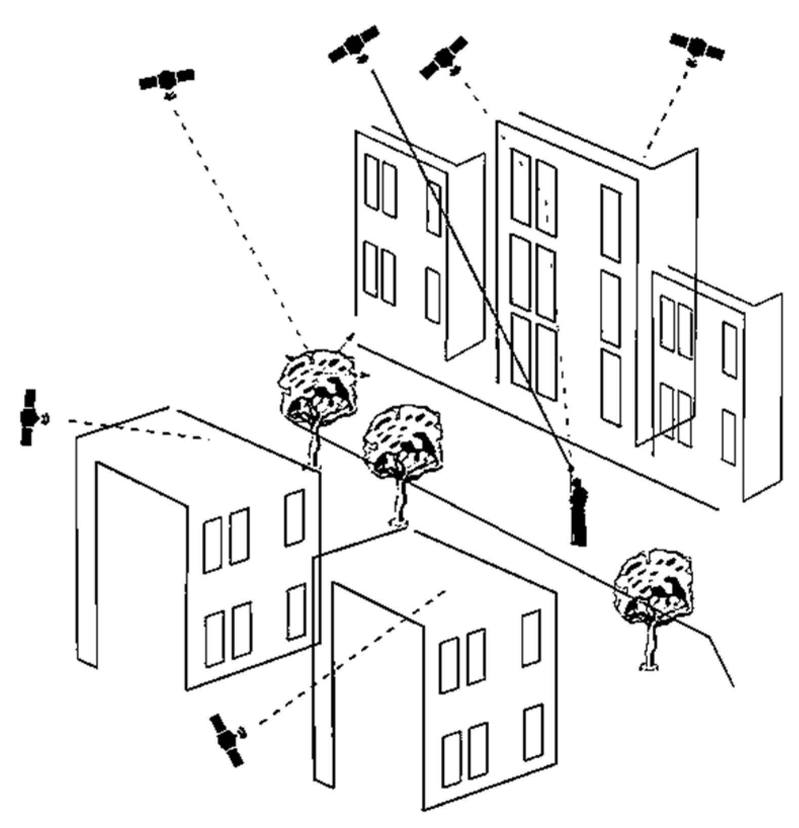
GNSS positioning relies upon measuring the time difference of arrival between the signal broadcasted by the GNSS satellites and the time when this signal was received by the user [3]. In urban environments, the GNSS signal may be reflected or scattered by natural (i.e., trees) or artificial (i.e., buildings) structures interfering with the signal that reaches directly the receiver. This interference (multipath) reduces the accuracy and integrity of GNSS positioning. Furthermore, signal blockages caused by tunnels and/or limited satellite visibility (no open-sky conditions) pose additional challenges in the accuracy and integrity of GNSS positioning (Figure 1).
The existence of multi-constellation and multi-frequency GNSS receivers is essential to the optimal error resolution in urban environments. The availability of a high number of satellites will certainly improve the GNSS signal availability when using dual-frequency receivers, whereas some studies claim that multi-constellation will lead to an improvement in the performance of low-cost single-frequency receivers in urban environments [4]. However, the increased number of available GNSS satellites is not considered as a solution for GNSS positioning in urban environments [5], and other factors such as the distribution of the satellites, the observation noise [6], and the receiver design [7] need to be evaluated. Thus, even though the performance of multi-constellation GNSS positioning in an urban environment is improved with respect to independent system analysis [8], alternative techniques have also been proposed and implemented to further reduce the uncertainty of the positioning results in challenging environments such as angle approximation [9], shadow matching [10], multipath mitigation using 3D models [11], and statistical models [12]. The traditional surveying alternatives suffer from time-consuming methodologies and additional highly priced equipment in order to link GNSS or topographic network coordinates to the area under survey.
In the present study, a robust and responsive solution for ground coordinate measurements in environments where satellite signals can be obstructed is presented by using a customized Unmanned Aerial System (UAS or drone) as an intermediate. The proposed solution exploits the higher altitude of a UAS to gain better visibility towards GNSS satellites and subsequently improve GNSS positioning accuracy. The objective is to transfer this enhanced UAS positioning accuracy to the ground with a minimal loss of accuracy.
Several additional advantages through this solution may emerge: First, since the UAS will be at a higher altitude, its field of view may accommodate several consequent measurement points. Thus, mapping will not require multiple GNSS receivers or any other dedicated sensor on the ground when the surveying of multiple points is underway. Second, indoor positioning can be supported, in such cases when the customized drone can point into a building through its openings (e.g., windows, or doors). This means that a topographic transverse can be initialized in various coordinate systems depending on the GNSS board settings, i.e., get connected between outdoors and indoors. Third, the kinematic positioning of moving topographic poles may be supported, facilitating several other applications such as search and rescue and monitoring. Another advantage of the proposed solution involves the difference between the coordinates of the required point of measurement versus the actual point of measurement. In traditional surveying, topographic poles with reflectors need to be leveled and placed exactly over the point of interest. Smaller reflectors are also used and placed on corners but special care has to be given by the surveyor to estimate the exact offset (angular and distance) between the reflector and the point of interest. The proposed solution replaces this pole-reflector equipment with a marker that can be placed upon the required point with a minimal loss of accuracy. All in all, the overall solution, named Drones2GNSS, provides highly-accurate GNSS positioning without GNSS on the ground in areas such as urban canyons, under tree canopies or in open-pit mines.
This study, since it describes a novel and disruptive technique that may change the course of classic surveying, is presented in the form of a research concept paper and focuses on the description of the proposed solution, its architecture, a theoretical error budget analysis, and initial measurements to demonstrate its potential. Section 2 presents the general architecture of the proposed solution along with a theoretical error budget analysis and propagation of uncertainties induced by several constituents. Section 3 presents a qualitative and quantitative estimation of the overall error of the proposed approach. Section 4 includes initial experiments under a simulated environment and concludes with a discussion on the future work that needs to be performed to confirm that Drones2GNSS constitutes a viable, accurate, and cost-effective surveying approach for GNSS positioning in obstructed environments.
2. Architecture and Measurement Methodology
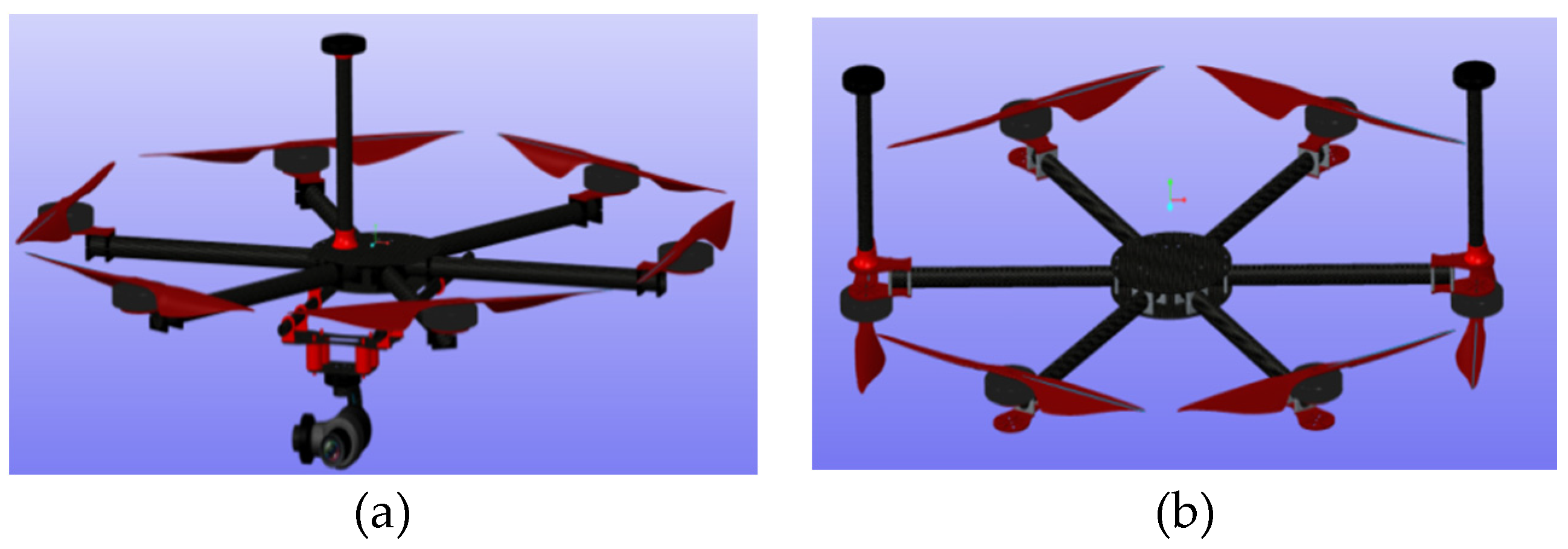
The conception of the Drones2GNSS architecture was partially based on existing knowledge from various scientific fields. For example, integration of digital imaging with range measurements provided mainly by lidar (light detection and ranging) sensors constitutes a common practice for more than two decades [13,14]. Furthermore, camera-based target detection and positioning has been also employed for search and rescue [15] and surveying applications, and also for obstacle avoidance, autonomous landing, navigation, etc. [16]. Moreover, fiducial markers (tags) have also been used for indoor localization of UAVs and landing [16]. Based on the authors’ prior experiences of UAS and surveying, along with operational factors such as cost and complexity of the system’s architecture, this proposed method includes the UAS and a single (or multiple) topographic pole that integrates a marker (i.e., Apriltag, ArUco, etc.). Note that no GNSS receiver is used on the pole. Alternatively, markers can be distributed or even attached to buildings, corners, or any feature in the area under consideration. The UAS, apart from the GNSS receiver, carries a gimbal incorporating a digital camera and a laser distance meter (Figure 2a). To further improve the accuracy of the UAS, positioning a dual antenna GNSS receiver configuration is also investigated (Figure 2b).
The measurement procedure initiates with the user placing the topographic pole or tag to the unknown point for measurement. The UAS reaches an adequate altitude to obtain the required signals from the satellites and computes its coordinates. The following measurements are then performed:
The UAS automatically locates and targets the marker on the tip of the pole through the camera. Thus, the relative 3D angles between the UAS camera and the marker are estimated, along with their distance, providing the coordinates of the surveying pole through image processing. Location in terms of coordinates is determined through the image geometry, gimbal orientation, and UAS GNSS readings. Optimized coordinate estimation is achieved through the central targeting of the marker in the camera’s field-of-view (principal point). To increase the geometric accuracy of the marker’s coordinates, the camera is calibrated for distortions, principal point shift, exact focal length, and more.
Under the image-based procedure, the gimbal angle measurement and especially distances are erroneous and when the UAS increases in distance from the pole, the precision of the point coordinate estimation is reduced. Therefore, a laser distance measurer is integrated in our system providing highly accurate distance measures. Concerning geometric calculations and coordinates, after detecting the marker, the gimbal will move the camera on board the UAS so that the marker is positioned in the center of the FOV-image. Through on-board frame relations, the range finder ray-casted endpoint is calculated on the marker’s surface and the distance between the marker and the camera’s image plane is measured. By using the current frame transformation relations, the captured distance is referenced to the GNSS coordinate system, and thus we are able to geo-reference the marker.
The angle estimation is now the main error constituent. To compensate for the angle precision measurements, the UAS makes a gradual circular movement around the marker-point of interest, providing continuous distance measures. Thus, triangulation is performed, as distances from known UAS coordinates are used to estimate unknown point coordinates as a local GNSS constellation triangulation procedure.
The above measurements are employed irrespectively of the GNSS processing method used to extract the UAS coordinates. The UAS coordinates may be calculated using either post-processing or real-time-kinematic techniques such as the conventional double-differencing with a local base station or a network service or the real-time precise point positioning technique [17].
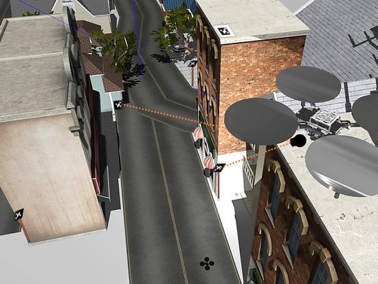
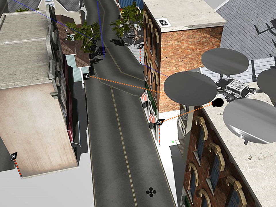
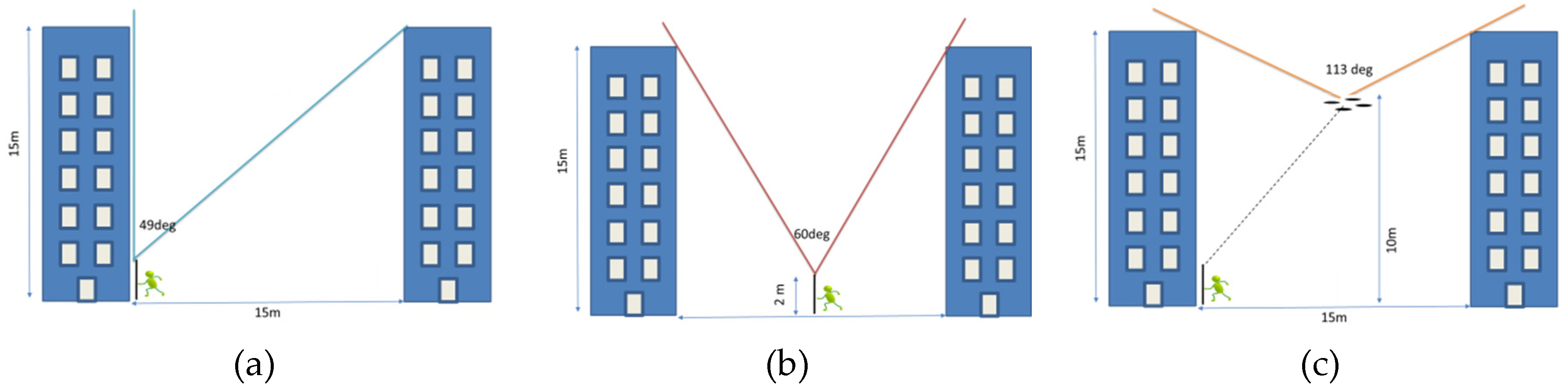
Figure 3 provides a schematic illustration and a two-dimensional scenario of the Drones2GNSS concept. Let us assume that a surveying engineer needs to measure the base of a 15 m-high building that lies on the left side of a 15 m road whereas another 15 m-high building lies on the opposite side of the road. With this particular two-dimensional geometry the effective field-of-view towards GNSS satellites is 49 degrees (Figure 2a). Even when the user stands on the middle of the road, the effective view is around 60 degrees (Figure 2b). If the UAS flies at an altitude of 10 meters then its visibility to GNSS satellites increases to 113 degrees.
More demanding conditions occur in vegetated areas, steep geomorphological zones, and areas with tall buildings or narrow streets, which occur frequently in historic and archaeological settlements.
2.1. Unknown Point Coordinate Determination
In this section, we present how the coordinates of the unknown point on the ground are to be estimated with respect to the coordinates of the GNSS receiver on-board the UAS. The camera and the range finder are installed on the gimbal that has three degrees of freedom, implying that it supports 3-axis stabilization corrections.
The gimbal’s frame origin is located on the middle point of its mounting mechanism to the UAS and its initial orientation is strafed as the UAS is facing frontward. The relative position (offset and rotation) of the gimbal’s origin with respect to the GNSS antenna is accurately known, thus the gimbal’s global coordinate system is also known. Each sensor measurement (tag pose from the camera and distance measurement from the range finder) can be referenced in each connected image frame and, subsequently, to the gimbal global coordinate system.
Assuming that {} is the global gimbal coordinate system and {} a local frame on the gimbal system, the latter is expressed as,
where, is the rotation matrix that describes frame {} relative to {} and is the vector that locates the origin of the frame {} in the {} coordinate system. Thus, in order to map a point which was spatially described by the frame {} to the frame {}, we define the transformation matrix,
So,
The point is described in global gimbal coordinates in frame . in addition, for the inverse spatial mapping, the inverse of the homogeneous transform is employed:
Let us now estimate the coordinates of the unknown point (B) with respect to the known UAS GNSS antenna coordinates (A). We define: tgnss the GNSS antenna offset w.r.t. the UAS center of mass, rgnss = rUAS the rotation of the GNSS antenna that coincide with the rotation of the UAS center, tgim and rgim the offset and the rotation of the gimbal w.r.t. the UAS center respectively, tcam and tdis the offset between the camera and the gimbal and the range finder w.r.t. the camera respectively. The rotation of the camera rcam and the range finder rdis are assumed to coincide with rgim, while the range finder’s measurement is defined as ddis.
The coordinates of the unknown point as given by the range finder measurement in its local coordinate system is given as . Given that rdis = rgim the range finder’s rotation w.r.t. the UAS center is given as . Then, the coordinates of the unknown point w.r.t. the UAS center need to be multiplied with the matrix T to correct for the offset and rotation
where corresponds to the overall offset of the range finder and camera system w.r.t. the UAS center and is given as the sum of tgim plus tdis plus tcam.
Finally, the global coordinates of the unknown point are given as:
2.2. Error Constituents
This section presents an analysis of the main sources of uncertainty in the positioning approach. Firstly, we assume that the offset between the GPS antenna, the UAS center, the camera’s focal point, and the range finder zero reference can be measured with an overall accuracy better than 5 mm. Thus, the accuracy of the measurements carried out by the on-board payload has to be estimated.
For the purpose of the present analysis, the marker is placed on a vertical surface away from the UAS. The camera is used to locate the marker’s central point. Then the gimbal rotates the range finder to focus on this central point. The 2D (x, y) location of the unknown point is given as:
where: is distance as measured by the range finder, the offset between the range finder and the UAS center, the offset between the GNSS antenna and the UAS center, the coordinate of the UAS GNSS antenna as derived by GNSS processing, the rotation angle as measured by the gimbal w.r.t. its initial position and the angle between the range finder w.r.t. horizontal plane.
The variance of Equation (7) is given by:
Assume Z is a random variable that follows normal distribution with mean and standard deviation μ and σ respectively (. Then, the expected value (mean) and the variance (Var) of cos(Z) and sin(Z) are given by the following:
Considering that the difference of two random variables A, B also follows a Gaussian distribution:
Then the expanded formula for the variance of is:
where μr, μd, μgps are the mean values of the angle measured by the gimbal, the distance is measured by the range finder and the GNSS derived position respectively and is the standard deviation of the GNSS derived position. By using the previous equations together with the mean and variance of the random variables, we can theoretically calculate the variance of (Equation (15)). Similar variance estimation is also valid for Equation (8).
For example, if we assume that the UAS is in horizontal position (thus θ and the mean of value of the gimbal is zero) and the variance of every random variable equals 0.012 (1 cm standard deviation) for location based variables, and 0.00352 (0.20° standard deviation) for angles, then Equations (7) and (15) result in:
In the following Section the impact of these error constituents is evaluated to identify those that are more critical for the precise determination of the unknown point coordinates.
3. Proof of Concept and Results
A numerical estimation of the uncertainty of the Drones2GNSS approach is given by assigning values in the variables present in Equation (15). For the sake of a concise solution, some assumptions were made. More specifically: (1) the UAS is considered to be in a horizontal position thus the mean values of the angle is zero, (2) the range finder is considered to measure at an angle of 45 degrees w.r.t. the UAS horizontal axis (θ = 45°), and (3) the offsets of the range finder and the GNSS antenna w.r.t. the gimbal center of mass are set to (−0.30, −0.30) and (0.30, 0.30) respectively.
The results of Equation (10) are evaluated for three different cases:
- Case 1: The standard deviation of the angles varies within the range of 0.2° to 1.0° with a step of 0.2°. The standard deviation of any offset involved is set to 1 cm. The distance to marker (DTT) ranges between 5 m to 20 m (step 1 m);
- Case 2: The standard deviation of the angles is set to 0.2° whereas the standard deviation of the offsets varied in the range 0.5 cm to 10 cm (step 5 mm). The DTT varies in the same range as before.
- Case 3: The same as Case 2, except the standard deviation of the angles that is now set to 0.1°.
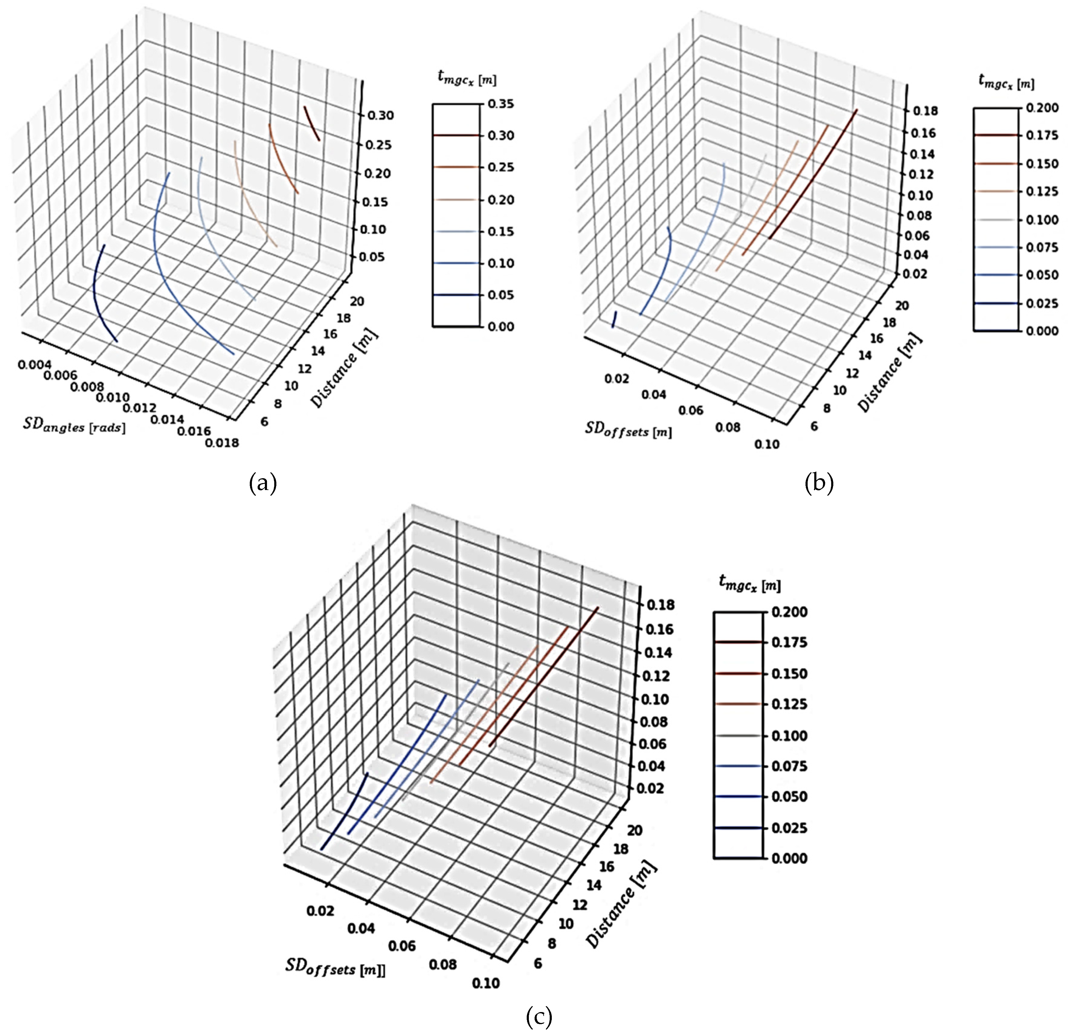
Figure 4 presents the standard deviation of for each of the above cases.
In the first case, the standard deviation of the angle varies from 0.004 to 0.020 radians. This corresponds to a standard deviation of 0.2 to 1 degrees that can be obtained by several commercial IMU (Inertial Measuring Units) [18] or encoders [19]. We have visualized the contours for certain values of the standard deviation of the error in the estimation of the marker. We observe that distance is affected by the angle; bigger distances increase the standard deviation of the error. For example, for a distance of 15 meters, we need an angle error of around 0.2 degrees to achieve a standard deviation of 0.05 m. By lowering either the distance or the angle error, we get a standard deviation lower than 0.05 m. Any combination of distance and standard deviation of the angle error that is placed to the left of the contour for 0.05 m standard deviation will lead to lower standard deviations for the resulting estimation error.
In the second case, we observe that for larger values of standard deviation in the distance offsets, the standard deviation of the error does not change significantly with distance. To achieve a standard deviation of less than 0.05 m, the standard deviation of the location error should be approximately 0.01 m, so that the distance can reach 15 m.
In the third case, because the standard deviation of the angle error is lower, we can tolerate greater distances for the same error values in the location error. For example, for a standard deviation of 0.01 m for the location error, we can achieve a standard deviation of less than 0.05 m at a distance of 20 m. Since the angle error has a smaller standard deviation, we conclude from the contour lines that the distance does not affect the standard deviation of the error of the marker estimation for even smaller values of the standard deviation of the location error than before.
4. Discussion and Conclusions
GNSS positioning accuracy in urban canyons and under tree canopies becomes degraded, as the satellite signal is obstructed by buildings and/or dense vegetation. This factor constitutes a major problem for surveying engineers that have to find time-consuming and expensive solutions to gain centimeter positioning accuracy. To confront this challenge, a system that ensures an acceptable accuracy in these environments without using any GNSS receiver on the ground was proposed. The system is comprised by a drone equipped with a GNSS receiver, a digital camera, a gimbal, and a laser distance measurer. It is used to retrieve the coordinates of a topographic pole where a known marker pattern is attached. The applicability of this methodology is quite comprehensive, as by solving this actual engineering problem a novel surveying method will be established for occluded environments, where there is no current generalized solution. To verify the broadness of such a solution, we have to take into consideration the frequency and modality of surveying studies that encounter such environments. A plethora of occluded areas exist, including sparse forest areas, geomorphology challenging areas such as steep slopes and gorges, historic cities and archaeological sites where roads are usually narrow, and dense urban districts where buildings are quite tall. From our experience in surveying, at least 70% of the topographic studies we are conducting include such obstructed areas where there is no easy resolution, and we are obliged to revert to the classic total station and transverse methodologies which involve time-consuming field work and expensive equipment.
Therefore, this study demonstrates quite a large impact, as it may change the way surveying is conducted. It provides a clear, feasible solution for a common mapping problem, and it improves on other, less typical applications. For example, in the case of an indoor mapping application Drones2GNSS may establish a series of control points, given that these points are visible from the UAS through a window or other opening. In addition, for search and rescue applications, by substituting the marker with a thermal signature of a person in need, or a human image pattern, we can actually provide the real coordinates in real time even under movement. Other, future work implementations may involve a swarm of UASs that can establish a local GNSS network, providing seamless coverage in occluded areas. Most importantly, when this methodology gets fully operational, it may replace most common topographic measurements.
In the present paper, the general architecture of the Drones2GNSS positioning approach is presented along with qualitative and quantitative analyses of the error constituents. These analyses show that the standard deviation of the error in transferring the UAV positioning accuracy to the ground unknown point is in the order of 2 cm in several combinations of angle, offset measuring accuracy, and distances to the markers. For example, when the distance to the marker is 10 m and the standard deviation in angle measurements is 0.1°, the measured offset error is 1 cm, which is within the cm-level accuracy. Note that this theoretical accuracy does not take into account the accuracy of positioning the UAV itself, which will certainly introduce some level of uncertainty. Furthermore, several assumptions were made, such as the horizontal (i.e., stable) position of the UAS which practically will not be the case. However, this does not significantly impact the proposed solution as the on-board GNSS receiver is able to update the positioning of at a 5–10 Hz rate, while the point of interest is identifiable in several frames of the camera imagery. It is also noted that software-wise, the measurements take place only when the range finder aims the marker in the center, and only then the GNSS position is acquired, in order to achieve maximum cohesion. Nevertheless, this proof-of-concept paper paves the path towards a more detailed investigation and more meticulous budget estimation of the proposed solution.
At this stage, the Drones2GNSS system is able to locate markers and extract their coordinates with respect to the gimbal coordinate system. This constitutes the most important step towards the implementation of the overall positioning. Optimization experiments in simulated and laboratory environments were conducted through various combinations of cameras and range finders. These initial experiments show the feasibility of the method and provide the reliability for a fully autonomous solution. Furthermore, the utilization of simultaneous localization and mapping algorithms is also under investigation to reach a competent level of accuracy through the UAS camera alone.
Author Contributions
Conceptualization: P.P.; Methodology: P.P. and A.T.; Software: D.C. and D.T.; Hardware: D.C.; Writing—original draft preparation, A.T. and D.T. and D.C.; Writing—review and editing, P.P. and A.T.; Funding acquisition, P.P. and A.T. All authors have read and agreed to the published version of the manuscript.
Funding
This research and the APC have been co-financed by the European Union and Greek national funds through the Operational Program Competitiveness, Entrepreneurship and Innovation, under the call RESEARCH–CREATE–INNOVATE (project code:T1EDK-03209).
Conflicts of Interest
The authors declare no conflict of interest.
References
- Dabove, R. The usability of GNSS mass-market receivers for cadastral surveys considering RTK and NRTK techniques. Geod. Geodyn. 2019, 10, 282–289. [Google Scholar] [CrossRef]
- Zhu, N.; Marais, J.; Betaille, D.; Berbineau, M. GNSS Position Integrity in Urban Environments: A Review of Literature. IEEE Trans. Intell. Transp. Syst. 2018, 19, 2762–2778. [Google Scholar] [CrossRef] [Green Version]
- Ioannides, R.T.; Pany, T.; Gibbons, G. Known Vulnerabilities of Global Navigation Satellite Systems, Status, and Potential Mitigation Techniques. Proc. IEEE 2016, 104, 1174–1194. [Google Scholar] [CrossRef]
- Li, T.; Zhang, H.; Gao, Z.; Chen, Q.; Niu, X. High-Accuracy Positioning in Urban Environments Using Single-Frequency Multi-GNSS RTK/MEMS IMU Integration. Remote Sens. 2018, 10, 205. [Google Scholar] [CrossRef] [Green Version]
- Smolyakov, I.; Langley, R.B. Innovation: Low-cost Single-Frequency Positioning in Urban Environments. GPS World. Available online: https://www.gpsworld.com/low-cost-single-frequency-positioning-in-urban-environments/ (accessed on 26 July 2019).
- Pan, S.; Meng, X.; Gao, W.; Wang, S.; Dodson, A. A New Approach for Optimizing GNSS Positioning Performance in Harsh Observation Environments. J. Navig. 2014, 67, 1029–1048. [Google Scholar] [CrossRef]
- Schonemann, E.; Springer, T.; Dilssner, F.; Becker, M.; Enderle, W. Impact of receiver design on multi-constellation multi-frequency processing. In Proceedings of the 6th European Workshop on GNSS Signals and Signal Processing, Munich, Germany, 5–6 December 2013. [Google Scholar]
- Xi, C.; Cheng-Dong, X. Performance analysis of multi-constellation GNSS in urban canyons based on fuzzy comprehensive evaluation. In Proceedings of the 29th Chinese Control and Decision Conference (CCDC), Chongqing, China, 28–30 May 2017. [Google Scholar]
- Mahmoud, A.; Noureldin, A.; Hassanein, H.S. VANETs Positioning in Urban Environments: A Novel Cooperative Approach. In Proceedings of the 2015 IEEE 82nd Vehicular Technology Conference (VTC2015-Fall), Boston, MA, USA, 6–9 September 2015. [Google Scholar]
- Groves, P.D. Shadow Matching: A New GNSS Positioning Technique for Urban Canyons. J. Navig. 2011, 64, 417–430. [Google Scholar] [CrossRef]
- Zhang, S.; Lo, S.; Chen, Y.-H.; Walter, T.; Enge, P. GNSS multipath detection in urban environment using 3D building model. In Proceedings of the 2018 IEEE/ION Position, Location and Navigation Symposium (PLANS), Monterey, CA, USA, 23–26 April 2018. [Google Scholar]
- Wang, Y.; Chen, X.; Liu, P. Statistical Multipath Model Based on Experimental GNSS Data in Static Urban Canyon Environment. Sensors 2018, 18, 1149. [Google Scholar] [CrossRef] [PubMed] [Green Version]
- Schwarz, K.P.; El-Sheimy, N. Digital mobile mapping systems-State of the Art and future trends. In Advances in Mobile Mapping Technology; Tao, C.V., Li., J., Eds.; Taylor & Francis: London, UK, 2007; pp. 3–18. ISBN 0415427231. [Google Scholar]
- Lin, Y.C.; Cheng, Y.T.; Zhou, T.; Ravi, R.; Hasheminasab, S.M.; Flatt, J.E.; Troy, C.; Habib, A. Evaluation of UAV LiDAR for mapping coastal environments. Remote Sens. 2019, 11, 2893. [Google Scholar] [CrossRef] [Green Version]
- Sun, J.; Li, B.; Jiang, Y.; Wen, C. A camera-based target detection and positioning UAV system for search and rescue (SAR) purposes. Sensors 2016, 16, 1778. [Google Scholar] [CrossRef] [PubMed] [Green Version]
- Tomaštík, J.; Mokroš, M.; Surový, P.; Grznárová, A.; Merganiˇc, J. UAV RTK/PPK method-An optimal solution for mapping inaccessible forested areas? Remote Sens. 2019, 11, 721. [Google Scholar] [CrossRef] [Green Version]
- Li, Z.; Chen, H.; Yuan, P. Accelerating real-time PPP ambiguity resolution by incorporating multi-GNSS observations. Adv. Space Res. 2019, 63, 3009–3017. [Google Scholar] [CrossRef]
- Inertial Lab Home Page. Available online: https://www.unmannedsystemstechnology.com/company/inertial-labs/#5 (accessed on 16 March 2020).
- AMS Home Page. AS5048A/AS5048B Datasheet. Available online: https://ams.com/documents/20143/36005/AS5048_DS000298_4-00.pdf (accessed on 16 March 2020).
Figure 1.
Illustration of Global Navigation Satellite System positioning in urban environments. The presence of buildings and trees prohibit the direct detection of satellite signal. Thus, multipath and limited satellite visibility degrade the GNSS performance.
Figure 1.
Illustration of Global Navigation Satellite System positioning in urban environments. The presence of buildings and trees prohibit the direct detection of satellite signal. Thus, multipath and limited satellite visibility degrade the GNSS performance.

Figure 2.
The unmanned aerial system (UAS) segment with (a) a GNSS, camera, gimbal, range finder and (b) using a dual-antenna GNSS receiver.
Figure 2.
The unmanned aerial system (UAS) segment with (a) a GNSS, camera, gimbal, range finder and (b) using a dual-antenna GNSS receiver.

Figure 3.
Problem statement and the Drones2GNSS concept in urban environments (a) The user receives direct GNSS signals from satellites that are 49 degrees above the horizon when the unknown point is on the base of a building, (b) the effective field view increases to 60 degrees if the user stands on the middle of the road, (c) the Drones2GNSS concept where the accuracy of a UAS that at 10-m altitude thus observing GNSS satellites at 113 degrees is transferred to the ground.

Figure 4.
Graphical illustration of the standard deviation of the position of the unknown point for Case 1 (a), Case 2 (b) and Case 3 (c).
Figure 4.
Graphical illustration of the standard deviation of the position of the unknown point for Case 1 (a), Case 2 (b) and Case 3 (c).

© 2020 by the authors. Licensee MDPI, Basel, Switzerland. This article is an open access article distributed under the terms and conditions of the Creative Commons Attribution (CC BY) license (http://creativecommons.org/licenses/by/4.0/).
Share and Cite
MDPI and ACS Style
Partsinevelos, P.; Chatziparaschis, D.; Trigkakis, D.; Tripolitsiotis, A. A Novel UAV-Assisted Positioning System for GNSS-Denied Environments. Remote Sens. 2020, 12, 1080. https://0-doi-org.brum.beds.ac.uk/10.3390/rs12071080
AMA Style
Partsinevelos P, Chatziparaschis D, Trigkakis D, Tripolitsiotis A. A Novel UAV-Assisted Positioning System for GNSS-Denied Environments. Remote Sensing. 2020; 12(7):1080. https://0-doi-org.brum.beds.ac.uk/10.3390/rs12071080
Chicago/Turabian StylePartsinevelos, Panagiotis, Dimitrios Chatziparaschis, Dimitrios Trigkakis, and Achilleas Tripolitsiotis. 2020. "A Novel UAV-Assisted Positioning System for GNSS-Denied Environments" Remote Sensing 12, no. 7: 1080. https://0-doi-org.brum.beds.ac.uk/10.3390/rs12071080
Note that from the first issue of 2016, this journal uses article numbers instead of page numbers. See further details here.