Using Drones and 3D Modeling to Survey Tibetan Architectural Heritage: A Case Study with the Multi-Door Stupa


1
School of Architecture, Nanjing Tech University, Nanjing 211800, China
2
Key Laboratory of Urban and Architectural Heritage Conservation (Southeast University), Ministry of Education, Nanjing 210096, China
3
School of Architecture, Southeast University, Nanjing 210096, China
*
Author to whom correspondence should be addressed.
Sustainability 2018, 10(7), 2259; https://0-doi-org.brum.beds.ac.uk/10.3390/su10072259
Submission received: 28 May 2018
/
Revised: 18 June 2018
/
Accepted: 28 June 2018
/
Published: 30 June 2018
(This article belongs to the Special Issue Digital Heritage)
Abstract
:Tibet has an average altitude of 4900 m, a complex terrain, and unique climatic conditions. The technologies used to survey this country’s local architectural heritage must be portable, efficient, and versatile. Low-cost Unmanned Aerial Vehicles (UAVs) and Structure from Motion (SfM) algorithms can help satisfy these demands. Recent studies employing nadir images from low-cost UAVs and SfM algorithms have reported positive metric results (with centimeter-level accuracy) when modeling 2D objects (e.g., land, roofs, and facades). In Tibet, however, forming a complete 3D model of architectural heritage is highly preferable and doing so requires a camera network that can create nadir and oblique images with various baselines. This study compared the accuracies of surveying a Tibetan stupa using the UAV-SfM method compared with Ground Control Points (GCP) and Terrestrial Laser Scanning (TLS). The results indicated that the UAV-derived model is accurate enough for most surveying purposes (RMSE = 2.05 cm; 1/2000 of the stupa’s dimension). The accuracy and completeness of the 3D model allowed Historic Building Information Modeling (HBIM) and structural deformation analysis to also be undertaken. In addition, the stupa was integrated with geographic data (terrain and infrastructure) for visualization, management, and evaluation purposes at a larger scale. Considering the low cost, portability, and completeness offered by UAV and SfM, this tool offers promise for surveying Tibet’s architectural heritage.
1. Introduction
1.1. Surveying Tibetan Architectural Heritage
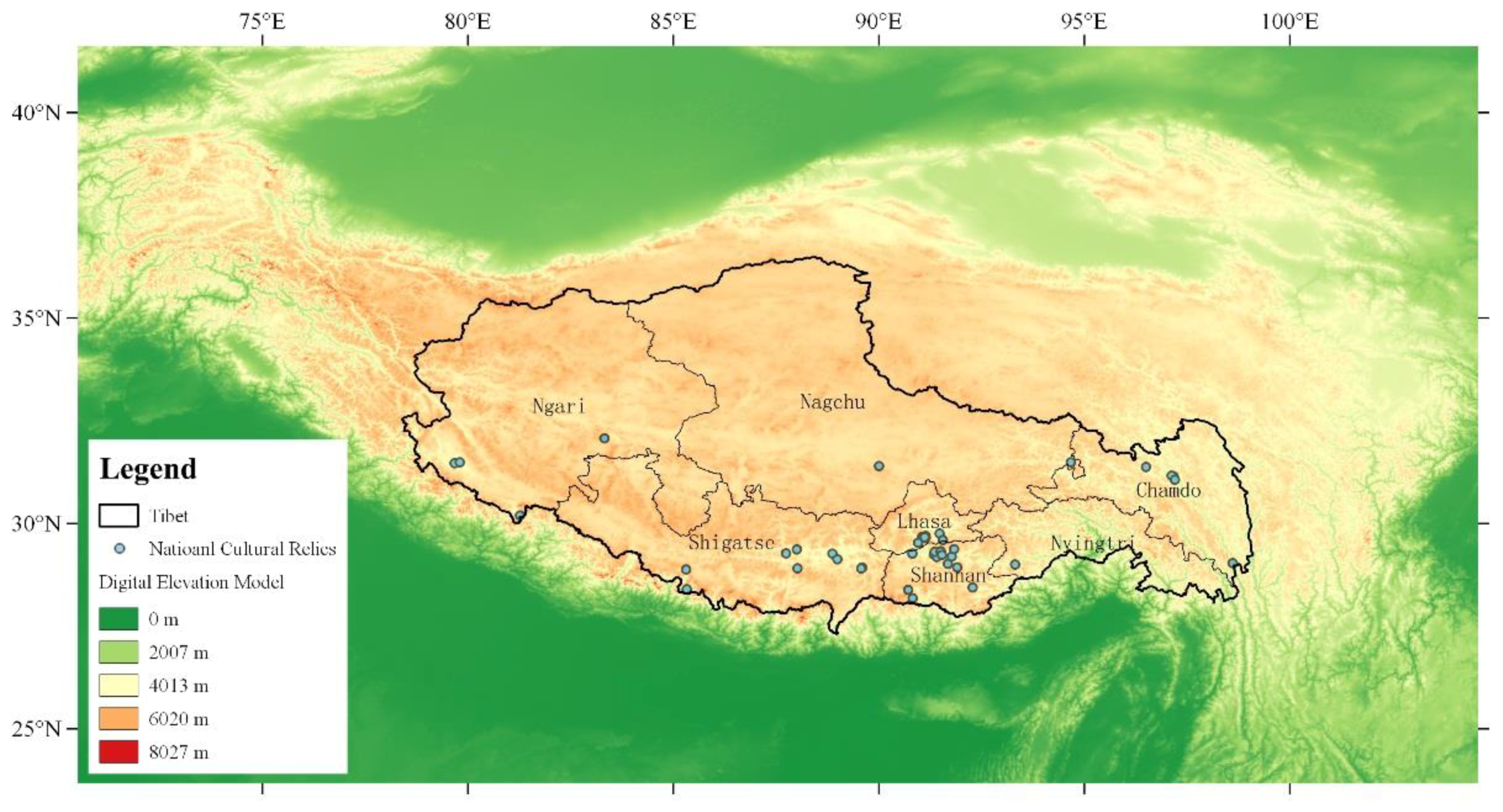
A major constraint to local heritage conservation in Tibet has long been the lack of reliable surveys of the area’s architectural heritage. Located on the Qinghai–Tibet Plateau, Tibet is the highest region on Earth with a complex terrain at an average altitude of 4900 m that extends over one-eighth of China’s land territory (Figure 1). Tibet’s unique geography created great difficulties for European explorers in the first half of the twentieth century [1,2], as well as for Chinese researchers even after 2006 when the Qinghai–Tibet Railway was completed [3,4]. It takes 40 and 46 h, respectively, to travel by railway from Beijing and Shanghai (two centers of Chinese scientific research) to Lhasa, the capital of Tibet. To travel from Lhasa to Ngari, the western-most prefecture in Tibet, it requires another two days by road. Once fieldwork has begun, surveyors face challenges including lack of oxygen, strong sunshine, and unstable weather. These harsh natural conditions necessitate the use of appropriate effective survey technologies.
Since the 1990s, optical measurement technologies such as terrestrial laser scanning (TLS) have been widely used in high-definition surveys of architectural heritage [5,6]. Thanks to TLS, millimeter-level accuracy and resolution as well as three-dimensional geometry have helped researchers re-examine the errors and omissions introduced in previous surveys by the limitations associated with manual measurements. New insights into Chinese architectural history and heritage conservation were generated by such improved survey results [7,8]. From a domestic geographical perspective, TLS has been used mainly on the North China Plain (i.e., Beijing, Tianjin, and Shanxi), an area that has been a research focus since the pioneering work of first-generation Chinese architectural historians in the 1930s [9].
However, these surveying technologies cannot easily be transferred for use in Tibet [10]. In addition to its harsh natural conditions, Tibet’s architectural typology ranges from monasteries to castles and stupas, which are quite different from the wooden temples on the North China Plain. Many local architectural heritage sites cover large areas and are closely related to the neighboring environment (e.g., terrain, water, and vegetation). TLS cannot be used effectively in Tibet for the following reasons: (1) scanners are generally too bulky to carry, especially considering altitude sickness; (2) taking field measurements is time-consuming and millimeter-level accuracy is not necessary in many cases; (3) TLS coverage is limited in distance and angle, resulting in incomplete data acquisition; and (4) the TLS’s internal camera does not have sufficient color depth to document the chromatic scales of the paintings on the facades that are quite common in Tibet. For these reasons, in addition to using TLS (for high-definition surveys) and manual measurements (for preliminary surveys), surveys of Tibet’s architectural heritage must have access to a portable and efficient method that provides wide coverage without suffering a large decline in accuracy.
1.2. UAV-SfM Method for Architectural Heritage Surveys
The integration of low-cost unmanned aerial vehicles (UAVs) and structure from motion (SfM) algorithms facilitates the documentation of architectural heritage by providing greater flexibility and more extensive coverage [11,12,13]. Although a UAV system embedded with multiple cameras is more efficient in acquiring images, it is also much more expensive, and cannot be used in most countries without permission [14]. Low-cost UAVs (~10,000 RMB) make low-altitude image acquisition affordable and manageable for users with limited budgets, and SfM algorithms developed by the computer vision community automate the process of image-based modeling [15,16,17,18]. The combined use of UAVs and SfMs enables the 3D modeling of large-scale and complex architectural heritage sites using image collections acquired at low cost and with high flexibility. Recent studies assessing the accuracy of the UAV-SfM method for architectural heritage surveying have discussed the following three factors: camera calibration, camera network, and Ground Control Points (GCPs) with known geographic locations.
- Camera calibration is a prerequisite for metric 3D reconstruction based on imagery. The camera’s interior parameters (e.g., principal points, principal distance, and radial lens distortion) are recovered during the process [19]. Depending on the research objectives, photogrammetry communities and computer vision communities have different approaches to camera calibration [20]. To achieve greater accuracy, the photogrammetry community prefers to conduct an independent calibration procedure prior to orienting the image. Coded targets are generally used to facilitate the manual or semi-automated detection of targets. The computer vision community employs simultaneous camera calibration and image orientation for automated applications. This procedure is known as self-calibration [21,22]. Coded targets are not required for self-calibration, since a feature-based camera calibration is conducted with the same images used to model the object. Feature-based camera calibration is preferred in architectural heritage surveying, because it speeds up the process of making field measurements and avoids having to place targets in inaccessible areas. Factors that are favorable to the accuracy of feature-based calibration include a convergent camera network with a large baseline-to-depth (B/D) ratio, image scale variations, and abundant detective features on survey objects [23].
- The camera network refers to the geometric relationships of the objects being surveyed and the image block. It exerts a decisive influence on the accuracy of feature-based calibration. The use of nadir images for 2D objects (e.g., roofs or facades) to plan a camera network is quite straightforward [24,25,26], because only a few factors such as image overlaps and ground sample distances (GSDs) should be considered. It becomes much more complex in the case of 3D objects that require a convergent camera network with oblique images [27]. Issues such as lens tilting, image scale, and illumination transitions may influence the metric quality [28]. Until now, most UAV-SfM-based surveying for architectural heritage has employed only nadir images. Roofs and facades are photographed and modeled separately. This approach is not practical for architectural heritage surveying in Tibet, given the complexity of objects and the required field efficiency. An all-in-one camera network that can produce a complete 3D model is the most common requirement.
- In aerial image-based surveying, external constraints such as Global Navigation Satellite Systems/Inertial Navigation Systems (GNSS/INS) data and GCPs are used to geo-reference 3D results and minimize possible camera network deformation during bundle adjustment [29]. The Global Positioning Systems (GPSs) embedded in low-cost UAVs are not currently reliable. GCPs are widely employed for greater accuracy and can be measured using a total station (an electronic/optical instrument used in modern surveying) on either manually arranged targets or natural features on the object being surveyed. Ideally, a total station can measure the target with an accuracy of about 1.5 mm, but instrument performance, distance to target, and human error may lead to different results. As reported by [30], a large number of precise and evenly distributed GCPs enhance the accuracy of UAV-SfM-based surveying.
Due to the required field efficiency and harsh conditions associated with surveying Tibetan architectural heritage, this paper uses a carefully designed convergent camera network with feature-based camera calibrations and abundant GCPs to ensure metric accuracy. This article assesses both the reliability of the UAV-SfM method for surveying architectural heritage and its viability as an affordable, portable, and flexible alternative to the use of TLS in Tibet.
2. Materials and Methods
2.1. Architectural Study Site
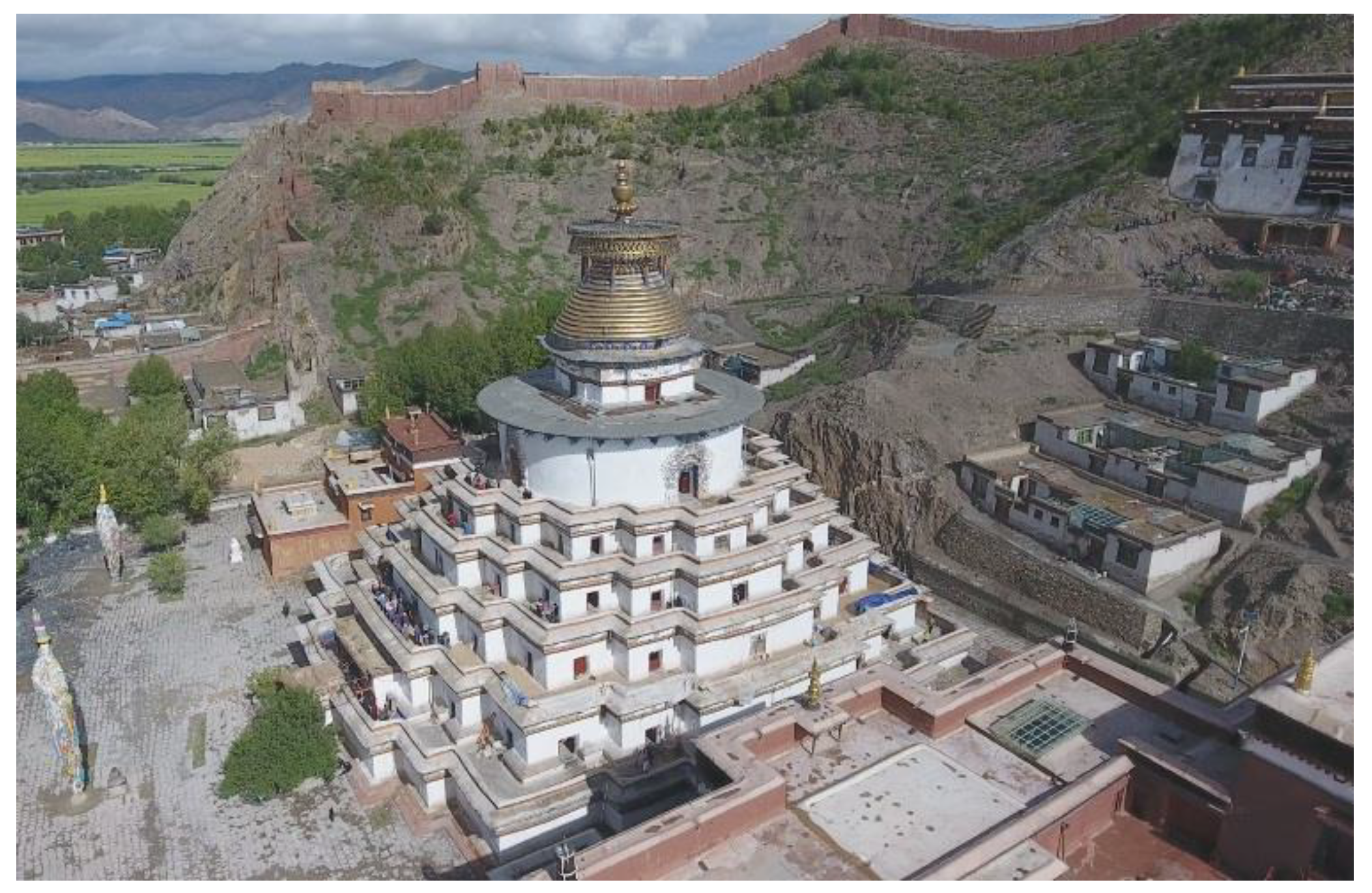
The architectural site used for this study was the Auspicious Multi-Door Stupa at Palcho Monastery (Figure 2) in Gyantse, Tibet. This monastery was built from AD 1418 to 1436. The Auspicious Multi-Door Stupa has nine floors, each floor with many chapels featuring magnificent wall paintings. The viability of TLS for surveying the Auspicious Multi-Door Stupa is quite limited. Due to the stupa’s shape, all of its exterior floors and most of its walls are outside the range of terrestrial scanning capabilities. In contrast, UAVs permit a no-dead-angle coverage of the structure.
2.2. UAV System and Image Acquisition
The UAV used was a DJI Phantom 4 quadcopter drone equipped with a camera (Table 1). Its 35 mm equivalent lens represents a remarkable improvement over previous versions, as the wide-angle lenses commonly used in low-cost UAVs capture images with severe radial distortions that reduce the metric quality of SfM reconstructions. The rotary wings allow takeoffs and landings in limited spaces and it can be operated by a single person. The battery permits a maximum flight time of 28 min in low-altitude areas, but because of the thinner atmosphere in Tibet, the maximum flight time drops to 15–20 min.
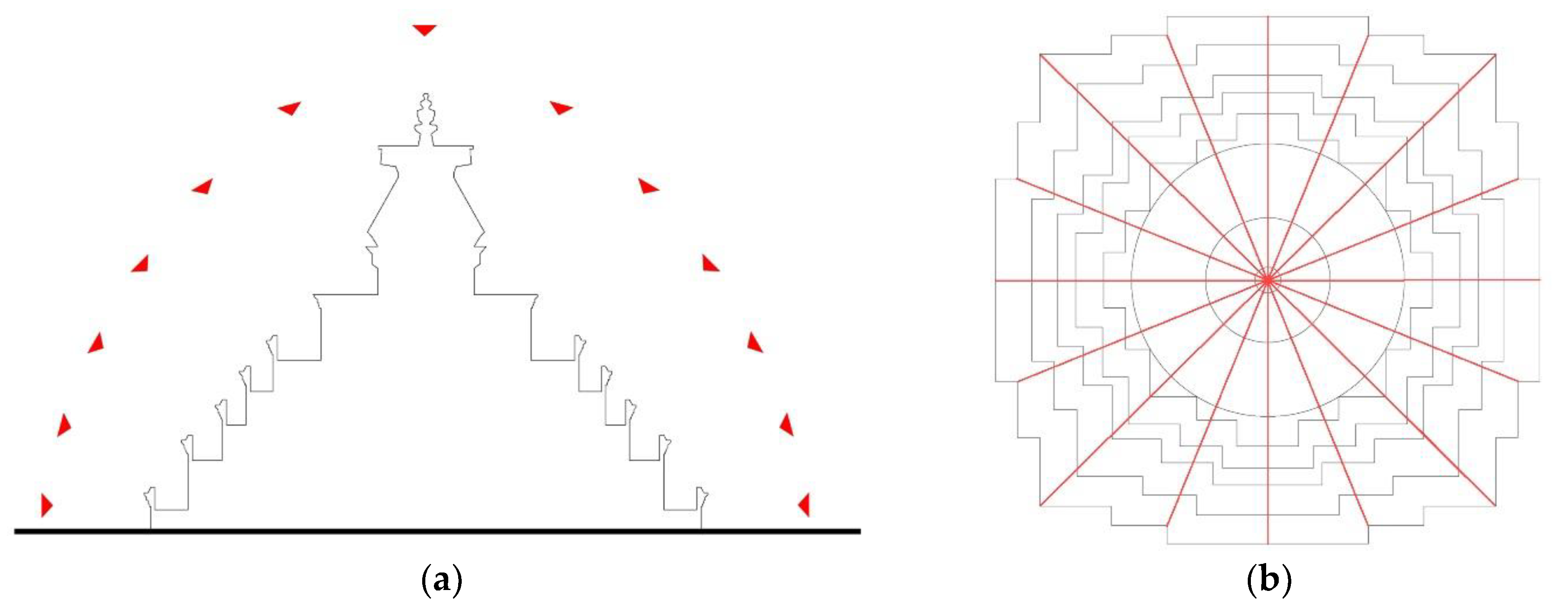
The most important task is acquiring images, since camera calibration and 3D reconstruction rely on the same set of images. The all-in-one camera network should satisfy feature-based camera calibrations, benefit metric accuracy, and guarantee sufficient image overlap. Several rules guide image acquisition: (1) the 3 × 3 rule of photogrammetry according to which every required surface should be covered by at least 3 images to guarantee completeness [31]; and (2) a larger baseline-to-depth (B/D) ratio to achieve greater metric accuracy. A convergent camera network with high image overlap was designed according to these rules (Figure 3). As the sunlight in Tibet is variable but intense, all images were taken during an overcast period to avoid the negative effects of changing illumination, including greater contrast between surface highlights and shadows as well as increased sensor noise. Although it is possible to remedy such deficiencies through an image pre-processing workflow consisting of color balancing, image denoising, and color-to-gray conversion [32], it is still worth ensuring consistent illumination conditions if an hours-long wait is an option.
The Phantom 4 drone allows autonomous flight following a planned route, but this was impractical due to the precision of onboard GNSSs and constant changes to the orientation of the lens. Thus, six flights were undertaken in manual mode, at the cost of incurring discrepancies between the actual camera network and an ideal camera network. To correct this problem, 365 images were captured; after removing redundant and blurred images, only 317 were used for modeling. Because of the camera’s small sensor size, distances between image capture positions and objects must be small to obtain a favorable Ground Sampling Distance (GSD). These distances range from 10 to 20 m with corresponding GSDs ranging from 4.4 to 8.8 cm.
2.3. Reference Measurements
This study used terrestrial surveying with a total station and TLS to evaluate the metric accuracy of the UAV-SfM method.
2.3.1. Measurement of GCPs
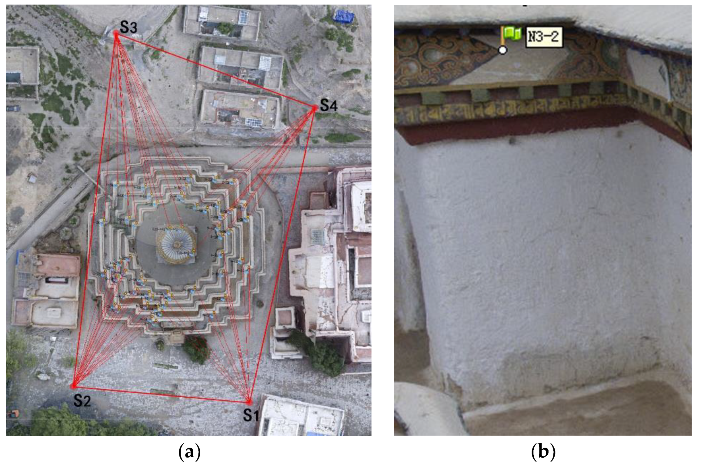
A measurement control network was established to obtain a GCP on each side of the Auspicious Multi-Door Stupa (Figure 4). Fifty-five evenly distributed GCPs were measured with a total station. Natural features (such as the corners of paintings) on the stupa were used, as they are more permanent than print markers for potential future measurements for purposes of comparison.
2.3.2. Laser Scanning
The metric accuracy of a UAV-derived model was compared to a ground truth model generated using TLS. The field measurements were carried out from 11 stations using high/medium resolution via a Leica ScanStation C10 and an external camera (Canon 60D). According to the manufacturer, the accuracy at this range is 4–6 mm. Use of the external camera dramatically decreased the required field time, but each station still required 10–15 min. The time required to complete the entire scanning process was about 6 h, mostly consisting of carrying the laser scanner and setting up pre-scan stations on the undulating terrain around the stupa.
2.4. Data Processing
Automated image-based modeling was performed using commercial Agisoft PhotoScan software. The automated procedures consisted of recovering image positions and the generation of sparse points and dense points, the generation of mesh, texture mapping, and the generation of Digital Elevation Models (DEMs). The 55 GCPs measured with total stations were manually assigned to the corresponding locations on the textured model. The geometric relationships between recovered image blocks and the 3D model were optimized using the GCPs’ coordinates. This procedure is known as Bundle Adjustment [33,34].
A watertight mesh surface was generated from the TLS-derived point cloud via the Screened Poisson algorithm [35], which ensured that the distance between the UAV-derived model and the TLS-derived model was computed through a points–mesh comparison instead of a points–points comparison. The points–mesh comparison guaranteed that the computed distance was the shortest distance between the two models that was not affected by the density of points.
3. Results
The accuracy of the UAV-derived model was assessed by comparing its results with those of the GCPs and TLS-derived model. After the SfM Bundle Adjustment was completed, an average deviation between the 55 GCPs and their corresponding points on the UAV-derived point cloud model was generated using the following equation:
where RMSE is the Root-Mean-Square Error, Xmodel,i is the ideal coordinates of a targeted point measured with a total station, Xobs,i is the actual coordinates of a targeted point in the UAV-derived model, and n is the number of GCPs. After the UAV-SfM method was applied to the stupa, the reported RMSE was 2.05 cm/1.615 pixels. This equates to 1/2500 the length (50 m) of the stupa. This level of accuracy is comparable to that of the TLS-derived model given the error-prone process of registering the multiple-station point cloud data.
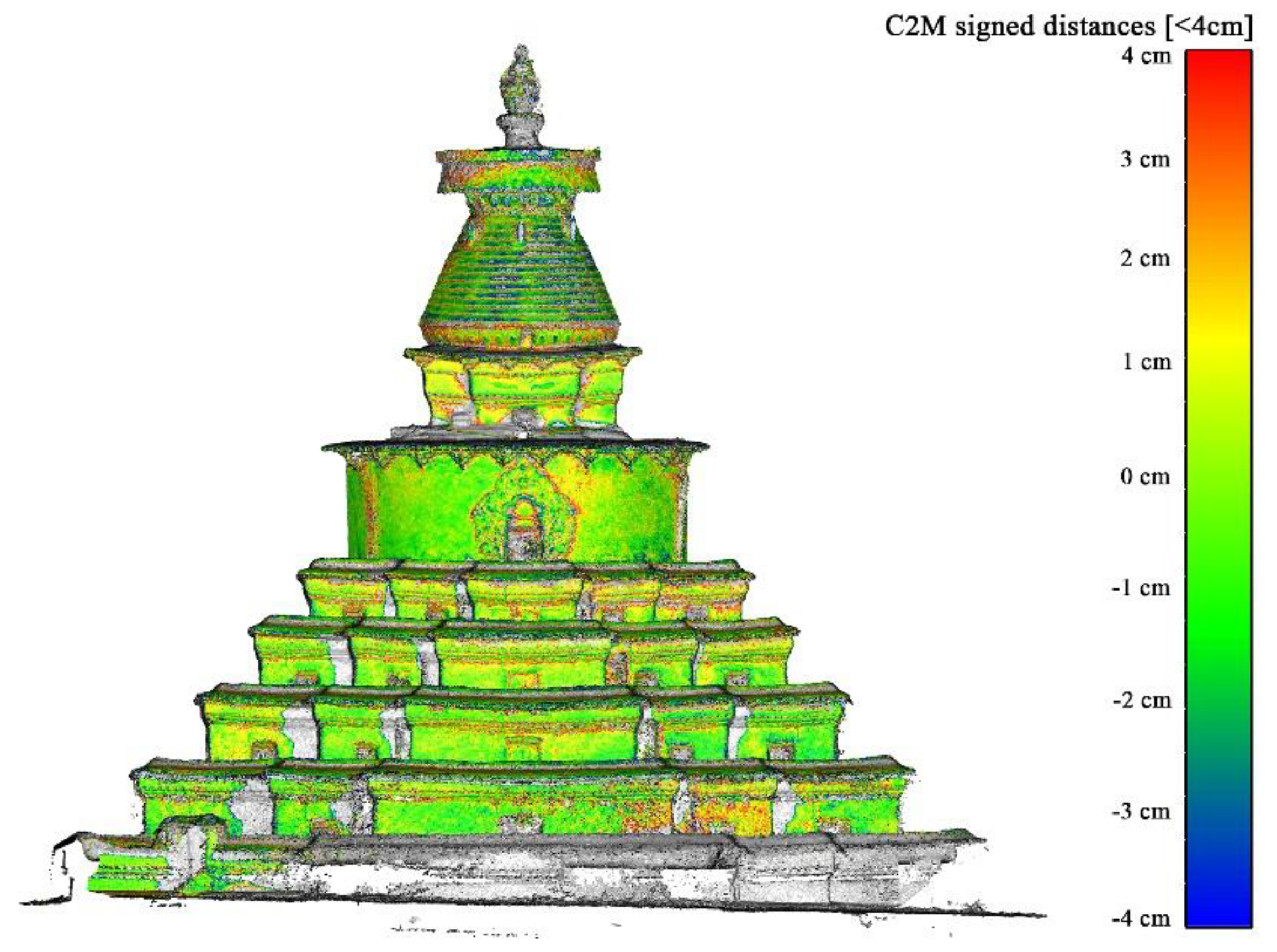
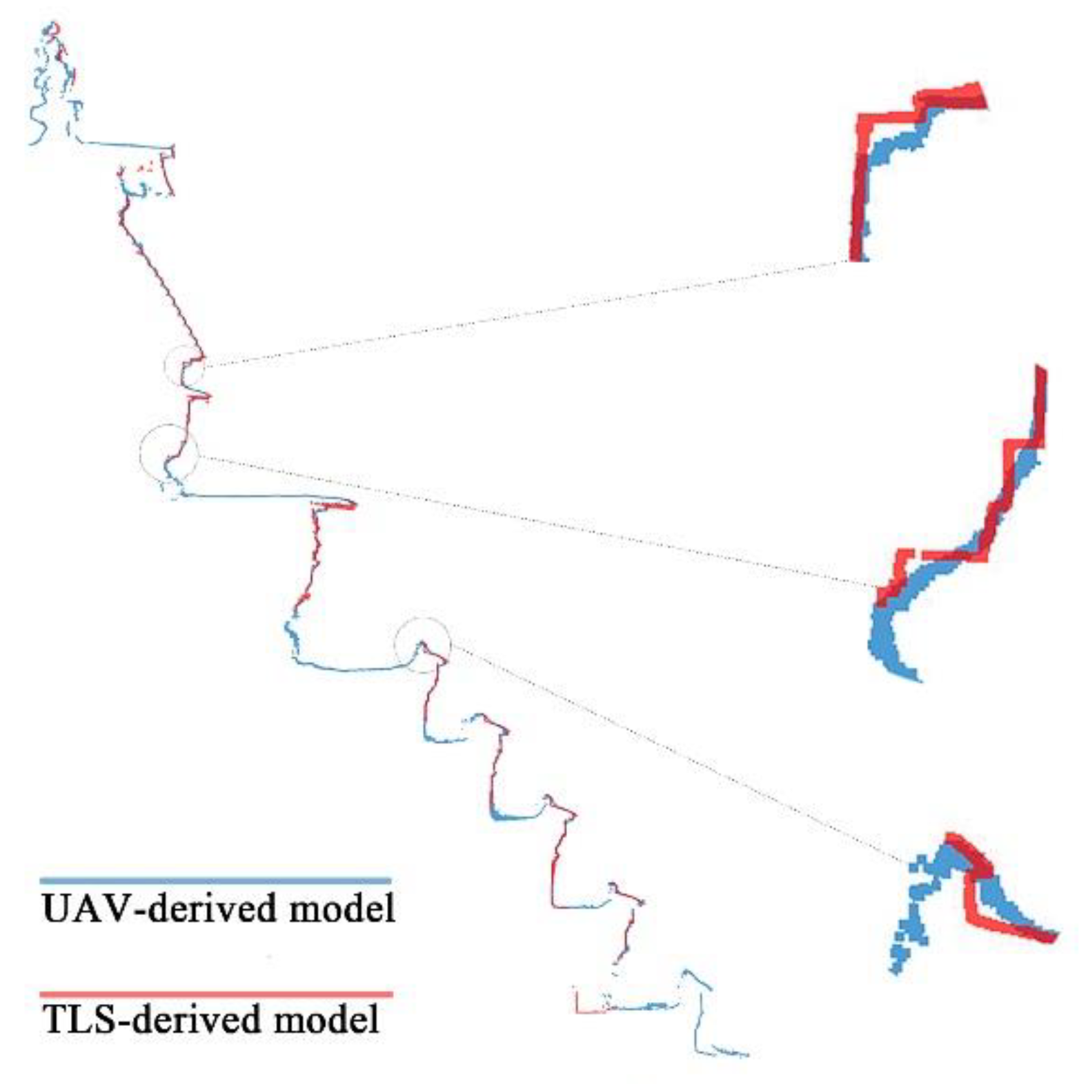
The UAV-derived model and the TLS-derived model were compared to conduct a more detailed evaluation. The closest distance to the TLS-derived mesh surface was computed and translated into scalar colors (green: zero; red and blue: maximum distance from zero) for each of the points in the UAV-derived point cloud. It is intuitively obvious that the UAV-derived model is very similar to the TLS-derived model (Figure 5). Most of the points in the UAV-derived model are green, indicating that their differences to the TLS-derived model are within ±1 cm. The large planar surfaces such as walls tend to be represented more accurately than brackets and moldings, because the UAV-derived model fails to represent most stupa components with sharp transitions. When vertical sections were extracted from the TLS-derived model and the UAV-derived model, it became evident that sharp transitions in the former had been replaced by filleted corners on the latter (Figure 6).
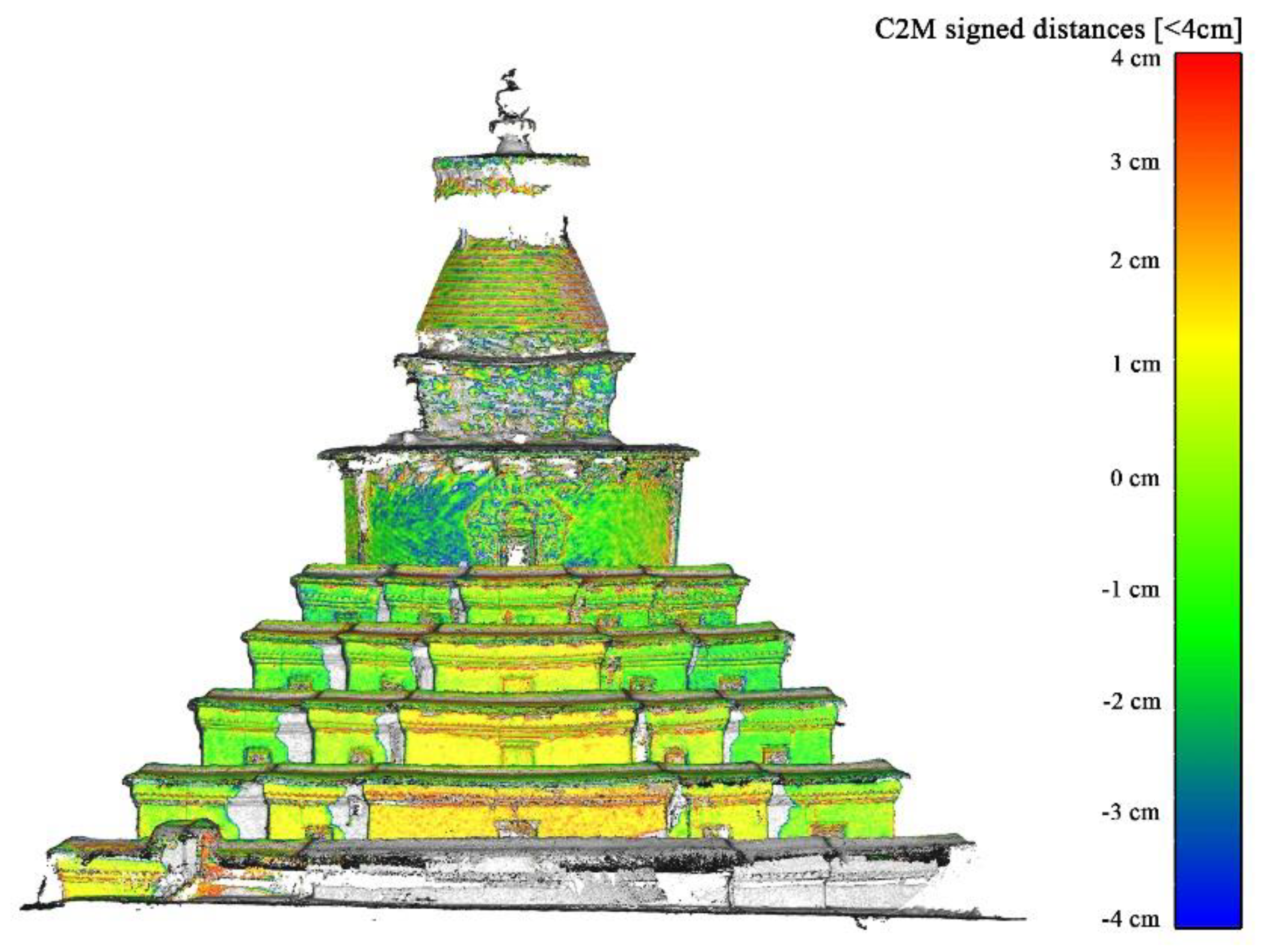
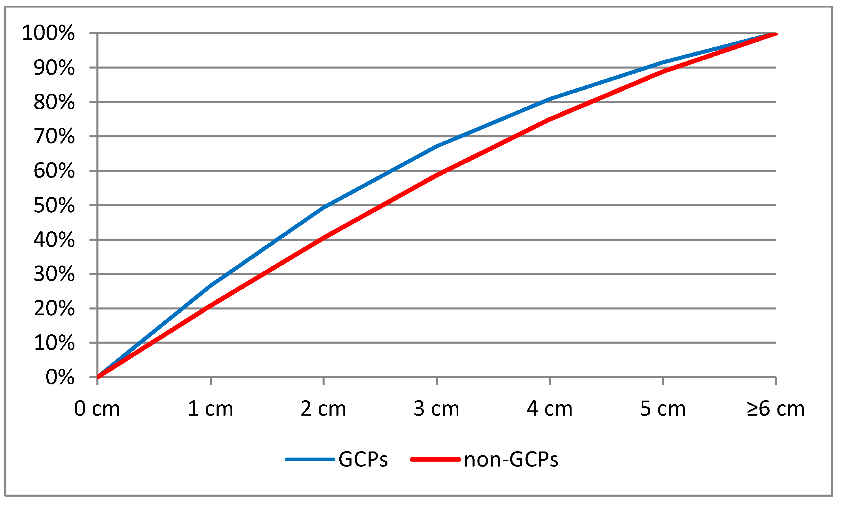
The use of GCPs is favorable to the SfM’s metric quality. Different usages of the GCPs with the same image set and SfM thresholds led to different levels of accuracy and completeness (Figure 5 and Figure 7). The GCPs improve the accuracy of image orientations and, consequently, the generation of dense point clouds. The contribution of GCPs in terms of accuracy is quantitatively illustrated by deviations to the TLS-derived model (Figure 8). In the model that used GCPs, 27% of the points are within ±1 cm, 67% of the points are within ±3 cm, and 92% of the points are within ±5 cm, while the relative rates in the model that did not use GCPs were 21%, 59%, and 89%.
The distribution of GCPs on the stupa also affects accuracy. Images of the upper parts of the stupa tend to be less accurate than those of the lower parts (Figure 5). Since a constant GSD was employed during image acquisition, the reason for these differences may be the absence of GCPs on the upper parts because of the lack of natural features. Another possibility is that the metal surfaces on the upper parts are smoother and more textureless than the coarse walls toward the bottom, creating problems for feature detection and feature correspondence in SfM reconstructions.
The results can be summarized as follows:
- This method can be used to achieve sufficient accuracy (1/2500) for most architectural heritage surveying purposes.
- The combined use of UAV and a total station can be an effective alternative to TLS when low-cost, portable, and fast on-field measurements are required (Table 2). Since the UAV-derived model fails to represent details on the stupa’s moldings, TLS is still necessary when extremely high accuracy and resolution are required.
- To guarantee accuracy and completeness, GCPs are necessary for UAV-SfM. A sufficient number of GCPs should be evenly distributed in 3D spaces.
4. Discussion
The convenience of the UAV-SfM’s data acquisition method offers excellent opportunities to represent and analyze Tibetan architectural heritage. Despite the absence of an interior model, having a complete exterior model of the stupa can nonetheless facilitate further applications.
Historic Building Information Modeling (HBIM) is a state-of-the-art application of raw point cloud architectural heritage data [36]. In contrast to conventional Computer-Aided Design (CAD) software, which represents data measurements in a collection of 2D drawings and 3D models, HBIM allows sustainable object-level data enrichment ranging from geometry to material and structure [37]. Once the gaps between the unsegmented point clouds and semantic-based modeling are bridged, an HBIM database that combines geometric complexity with semantic information will be of great value for data consumers (e.g., architects, architectural historians, and engineers). One of the main challenges of current HBIM methods is the loss of geometric accuracy during its translation into parametric BIM objects [38]. A mesh surface can accurately represent the irregular shapes of architectural heritage and their as-built conditions, but it is rarely manageable in a BIM environment. As most BIM software today is oriented for new design, a reasonable methodology recently proposed by [39] is based on hybrid modeling solutions: distinguishing the Level of Accuracy (LoA), Level of Detail (LoD), and Level of Knowledge (LK) with reference to existing technical standards and features of studied architectural heritage and then using suitable modeling techniques (e.g., 2D mapping, Loft, using a non-uniform rational B-spline format as a medium) to achieve the aims.
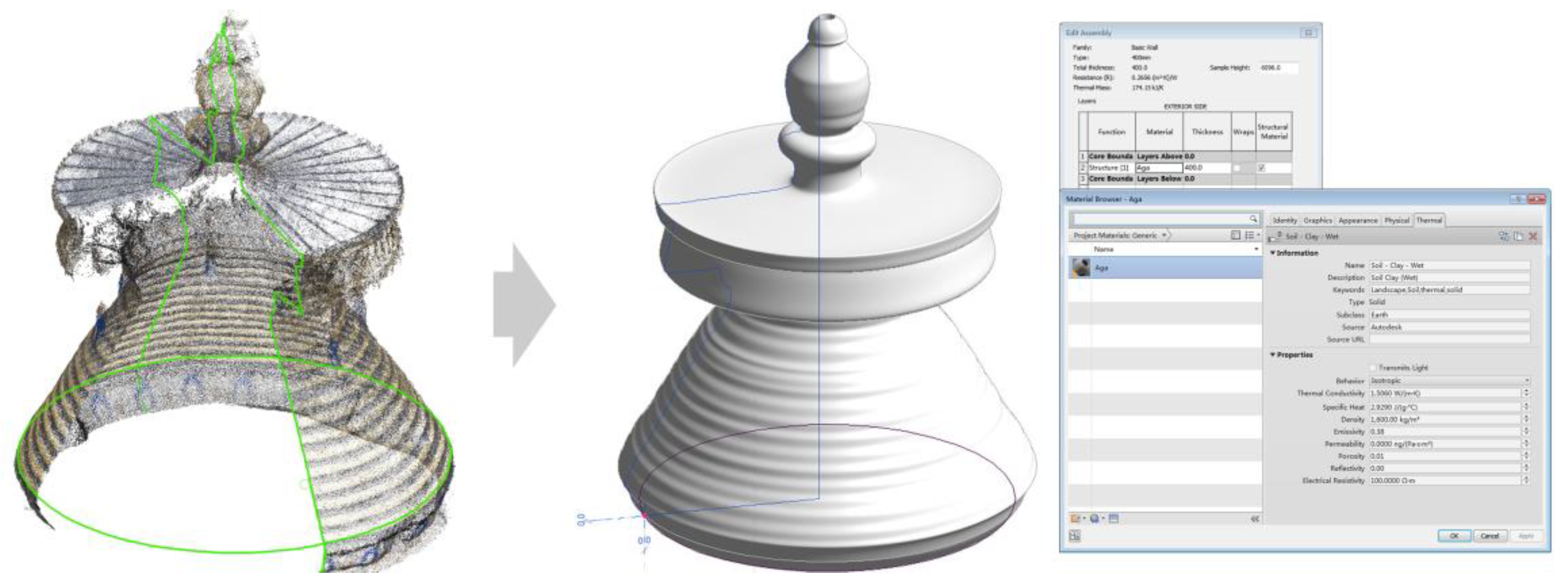
In this study, different modeling methods were employed depending on the required LoA and LoD, the geometry of the objects, and the expected degree of automation. For instance, a wall can be modeled simply by tracing the footprints of the point cloud and extruding them along the Z axis; the cone on top of the stupa is generated by revolving a profile along a path. Both the profile and the path are extracted from the point cloud with as-built geometry (Figure 9). In both approaches, accurate geometric shapes are integrated with semantic data ranging from a 2D graphic and 3D appearance to physical information (e.g., density, shear modulus, and yield strength) and thermal information (e.g., thermal conductivity, permeability, and reflectivity). The unknown wall thickness is defined as a parameter allowing potential input once it has been obtained. As the data ranging from material to decay are enriched, these models also facilitate further elaborations such as finite element structural analyses and energy simulations. In general, although the progression from point cloud to HBIM is still challenging, the UAV-SfM method offers a promising workflow at low cost and with high flexibility, both of which are of prime concern for architectural heritage surveying in Tibet.
The structural deformation of architectural heritage should be closely monitored. This task is conventionally conducted with point-to-point comparisons, in which coordinates of the relevant points are occasionally measured with a total station or a Differential GNSS to check for deformation. However, the results are affected by the distribution and sampling rates of the points. Point clouds provide an innovative method for monitoring structural deformation globally by comparing the data with a user-defined reference surface. As shown in previous surveys of the Auspicious Multi-Door Stupa and our practice [40], TLS coverage is quite limited. The settling patterns of each floor are outside the range of TLS. Carrying the scanner to each floor is impractical due to the much greater labor intensity required (at least 12 stations on each floor) and potential inaccuracies that could occur during the registration process. As shown above, UAVs permit a no-dead-corner coverage of the stupa and consequently generate a complete 3D model with centimeter-level accuracy (RMSE = 2.05 cm). This approach offers great convenience for the analysis of floor settling. In this case, the analysis workflow consisted of three steps: (1) segmenting the point cloud by floor; (2) defining reference planes for each segment (Figure 10a); and (3) calculating the closest points between segments and reference planes (in CloudCompare). Obvious settling was observed in the west of the first floor (Figure 10b). The degree of surface settling was found to be quite severe: the distance between the lowest points and the highest points on the same floor was almost 60 cm. This is probably due to the absence of measurement controls during the process of manually consolidating the floors, since local people sometimes volunteer to complete such tasks because doing so is considered a Buddhist virtue (Figure 10c). Further structural analysis and technological interventions are required in such cases. In order to evaluate the damage after an earthquake or monitor the deformation caused by inappropriate consolidation work, a new UAV-derived model can be quickly obtained using the presented method and compared with an existing model to generate intuitive 2D diagrams, 3D models, and 4D navigation, informing quantitative conclusions by filtering point clouds within certain ranges of scalar field values.
In recent years, free-access remote sensing data along with Geographical Information Systems (GISs) have been applied to cultural heritage management at a regional scale with increasing frequency. The remote sensing data available today include multi-spectral satellite imagery, DEMs, and shared research results from the remote sensing community (such as weather records, social statistics, and natural hazards). These data facilitate macroscopic management and an analysis of the natural hazards confronting Tibetan architectural heritage. In terms of study area and richness of captured data, this approach is an important supplement to terrestrial surveys. However, the gap between these two methods has yet to be filled.
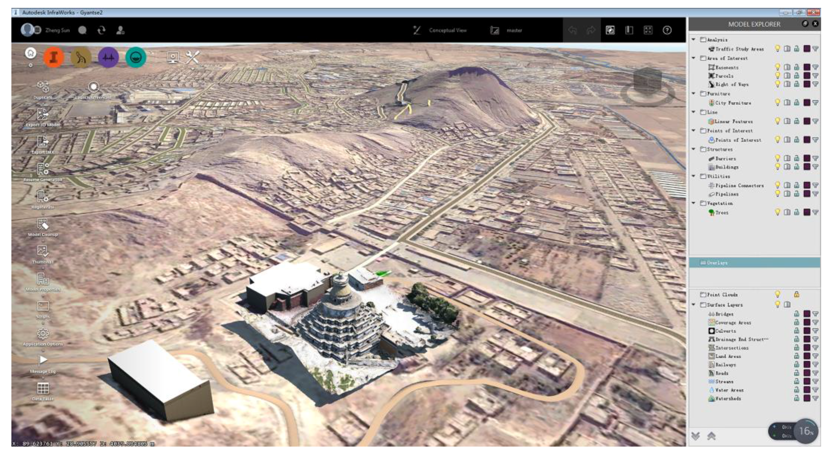
Free remote sensing data today are usually of medium resolution, for example, a pixel equalling 30 m per side. This resolution is of limited use when a single piece of architecture, instead of a region, is to be studied. The proposed SfM-UAV method provides a data acquisition method that falls between a terrestrial survey and remote sensing in terms of resolution, coverage, efficiency, and labor intensity. The generated orthoimage and DEM have up to centimeter-level resolution within square-kilometer-level coverage, and, as shown in this paper, the 3D model can achieve a sufficiently high level of completeness and accuracy. Consequently, it provides a digital representation of architecture and the surrounding environment with different LoD options, but also serves as a bridge between remotely sensed data and terrestrially surveyed data. For example, once a 3D model (point cloud, mesh, and the Industry Foundation Classes (IFC)-format model) of the Multi-Door Stupa has been obtained, it could be integrated with the geospatial terrain, streets, and water data automatically retrieved from Autodesk InfraWorks’ existing repositories (Figure 11), which include OpenStreetMap’s buildings, highways, and railways, or orthophotos from BingMaps and DEM (e.g., United States Geological Survey (USGS) or Aster datasets) [41,42]. Terrestrially surveyed results such as CAD drawings, SketchUp models, and point clouds can also be georeferenced with the existing data. Although this commercial software is originally intended for designing infrastructure, it is currently an ideal platform for combining semantic data with geospatial data, both of which are important for surveying Tibetan architectural heritage.
Tibet is one of the few places globally where the original natural environment around an architectural heritage site has not been highly altered by urban development. Thus, valuable information regarding architectural, archeological, and historical geography is embedded among the spatial relationships between buildings, terrain, water, and vegetation. The impact of new infrastructure on local architectural heritage (e.g., changes in sightlines, local climate, or construction vibrations) should be evaluated at a larger scale than a single building. Users of a geo-database are provided with an intuitive and friendly interface that allows 3D navigation and parametric modifications to the infrastructure. A complete database could be created by defining footprints, setting elevation patterns, and semi-automatically modeling the neighboring buildings that are not yet included in the database. A complete 3D terrain model with architecture provides source data for heritage management, and could also be used for travel guides and game development.
5. Conclusions
In conclusion, this paper evaluates the accuracy of the UAV-SfM method for surveying a Tibetan stupa and illustrates how the results could be elaborated in a next-step analysis and used for management purposes. Future development should include solving the problem of the missing interior model, potentially using a hand-held mobile laser scanning (MLS) system. According to [43], the accuracy and resolution (at the centimeter level) of this approach supports efficient and robust data acquisition given varying light conditions and visitor presence. Once the two models (UAV-derived and MLS-derived) are finely registered, the complete stupa model will open doors to further elaborations such as section drawing (with known thicknesses of walls and floors) and finding the center of gravity for structural analysis purposes. Another promising application of the method presented is the integration of the resulting bird’s-eye-view orthophotograph of architectural heritage with satellite imagery available in GISs. Changes to architectural heritage over time caused by natural or human factors over a wider range (e.g., mountains, rivers, and vegetation) could be detected and analyzed. Documenting these changes is very significant for Tibetan architectural heritage, where the relationship between individual architectural works and the neighboring geographical environment has been maintained for hundreds of years.
Author Contributions
Z.S. conceived and designed the study; Z.S. reviewed and edited the manuscript; Y.Z. and Z.S. collected and analyzed the data and wrote the paper. All the authors have read and approved the manuscript.
Funding
The study was funded by the National Natural Science Foundation of China (51708285); Natural Science Foundation of Jiangsu Province (BK20171009); and Open Fund of Key Laboratory of Urban and Architectural Heritage Conservation (Southeast University), Ministry of Education, China (KUAL1608).
Conflicts of Interest
The authors declare no conflict of interest. The funding sponsors had no role in the design of the study; in the collection, analyses, or interpretation of data; in the writing of the manuscript; and in the decision to publish the results.
References
- Tucci, G. Tibetan Painted Scrolls, 2nd ed.; SDI: Bankok, Thailand, 1999; p. 798. ISBN 10: 1878529390. [Google Scholar]
- Tucci, G. The Tombs of Tibetan Kings, 1st ed.; Mimesis International: Rome, Italy, 1950; p. 185. ISBN 10: 885752678X. [Google Scholar]
- Wang, Y.P. Applications of computer-aided digitization and visualization in architectural heritage preservation-three years experience of surveying cultural relics in Tibet. In Proceedings of the Fourth Symposium of Chinese Society of the Forbidden City, Beijing, China, 12 June 2004; pp. 148–152. [Google Scholar]
- Sun, Z.; Cao, Y.K. Applications of integrated digital technologies for surveying Tibetan architectural heritage: Three years experience. In Proceedings of the 22nd CAADRIA Conference, Protocols, Flows, and Glitches, Suzhou, China, 5–8 April 2017; Janssen, P., Loh, P., Raonic, A., Schnabel, M.A., Eds.; id: caadria2017_029. pp. 663–672. [Google Scholar]
- Blais, F. Review of 20 years of range sensor development. J. Electron. Imaging 2004, 13, 231–244. [Google Scholar] [CrossRef]
- Vosselman, G.; Maas, H.G. Airborne and Terrestrial Laser Scanning; CRC Press: Boca Raton, FL, USA, 2010; p. 320. ISBN 10: 1439827982. [Google Scholar]
- Liu, C.; Liu, M.Y.; Wang, X.Y. Interpretation of measurement data of Wanfo Hall’s wooden structure of Zhenguo Temple in Pinyao. Chin. Archit. Hist. Rev. 2012, 1, 101–148. [Google Scholar]
- Tang, Y.Y.; Du, B.Y.; Ding, Y.H. Exploration on Application of 3D Laser Scan Data in the Protection of Heritage Building. J. Beijing Univ. Civ. Eng. Archit. 2011, 27, 1–6. [Google Scholar]
- Jing, L.; Qihheng, W. History of Architectural Heritage Survey in China; China Building Industry Press: Beijing, China, 2017. [Google Scholar]
- Zhang, Y.Y.; Sun, Z. Usability of architectural heritage surveying technologies in Tibet. Huazhong Archit. 2018, 36, 52–56. [Google Scholar]
- Sun, Z.; Cao, Y.K. Data processing workflows from low-cost digital survey to various applications: Three case studies of Chinese historic architecture. Int. Arch. Photogramm. Remote Sens. Spat. Inf. Sci. 2015, 40, 409–416. [Google Scholar] [CrossRef]
- Trizzino, R.; Caprioli, M.; Mazzone, F.; Scarano, M. Applications of UAV Photogrammetric Surveys to Natural Hazard Detection and Cultural Heritage Documentation. In Proceedings of the EGU General Assembly Conference Abstracts, Vienna, Austria, 23–28 April 2017; Volume 19, p. 18091. [Google Scholar]
- Murtiyoso, A.; Grussenmeyer, P. Documentation of heritage buildings using close-range UAV images: Dense matching issues, comparison and case studies. Photogramm. Rec. 2017, 32, 206–229. [Google Scholar] [CrossRef]
- Petrie, G. Systematic oblique aerial photography using multiple digital cameras. Photogramm. Eng. Remote Sens. 2009, 75, 102–107. [Google Scholar]
- Hartley, R.; Zisserman, A. Multiple View Geometry in Computer Vision; Cambridge University Press: Cambridge, UK, 2000; p. 655. ISBN 10: 0521540518. [Google Scholar]
- Snavely, N.; Seitz, S.M.; Szeliski, R. Modeling the world from internet photo collections. Int. J. Comput. Vis. 2008, 280, 189–210. [Google Scholar] [CrossRef]
- Robertson, D.P.; Cipolla, R. Structure from motion. In Practical Image Processing and Computer Vision; Varga, M., Ed.; John Wiley: Hoboken, NJ, USA, 2008; p. 384. ISBN 10: 0470868562. [Google Scholar]
- Wu, C. Towards linear-time incremental structure from motion. In Proceedings of the 2013 International Conference on 3D Vision-3DV, Seattle, WA, USA, 29 June–1 July 2013; IEEE: Piscataway, NJ, USA, 2013; pp. 127–134. [Google Scholar] [CrossRef]
- Clarke, T.A.; Fryer, J.G. The development of camera calibration methods and models. Photogramm. Rec. 1998, 16, 51–66. [Google Scholar] [CrossRef]
- Remondino, F.; Del Pizzo, S.; Kersten, T.P.; Triosi, S. Low-cost and open-source solutions for automated image orientation—A critical overview. In Proceedings of the Progress in Cultural Heritage Preservation Euro-Mediterranean Conference, Limassol, Cyprus, 29 October–3 November 2012; Ioannides, M., Fritsch, D., Leissner, J., Davies, R., Remondino, F., Caffo, R., Eds.; Springer: Berlin/Heidelberg, Germany; pp. 40–54. [Google Scholar] [CrossRef]
- Pollefeys, M.; Koch, R.; Van Gool, L. Self-calibration and metric reconstruction inspite of varying and unknown intrinsic camera parameters. Int. J. Comput. Vis. 1999, 32, 7–25. [Google Scholar] [CrossRef]
- Fraser, C.S. Automatic camera calibration in close range photogrammetry. Photogramm. Eng. Remote Sens. 2013, 79, 381–388. [Google Scholar] [CrossRef]
- Barazzetti, L.; Mussio, L.; Remondino, F.; Scaioni, M. Targetless Camera Calibration. In Proceedings of the International Archives of the Photogrammetry, Remote Sensing, and Spatial Information Sciences, Trento, Italy, 2–4 March 2011; Volume XXXVIII-5/W16, pp. 335–342. [Google Scholar]
- Bolognesi, M.; Furini, A.; Russo, V.; Pellegrinelli, A.; Russo, P. Testing the low-cost RPAS potential in 3D cultural heritage reconstruction. Int. Arch. Photogramm. Remote Sens. Spatial Inf. Sci. 2015, 40, 229–235. [Google Scholar] [CrossRef]
- Ruggles, S.; Clark, J.; Franke, K.W.; Wolfe, D.; Reimshiiseel, B.; Martin, R.A.; Okeson, T.J.; Hedengren, J.D. Comparison of SfM Computer Vision Point Clouds of a Landslide Derived from Multiple Small UAV Platforms and Sensors to a TLS based Model. J. Unmanned Veh. Syst. 2016, 4, 246–265. [Google Scholar] [CrossRef]
- Thoeni, K.; Guccione, D.E.; Santise, M.; Giacomini, A.; Roncella, R.; Forlani, G. The Potential of Low-Cost Rpas for Multi-View Reconstruction of Sub-Vertical Rock Faces. Int. Arch. Photogramm. Remote Sens. Spatial Inf. Sci. 2016, XLI-B5, 909–916. [Google Scholar] [CrossRef]
- Nex, F.; Remondino, F. UAV for 3D mapping applications: A review. Appl. Geomat. 2014, 6, 1–15. [Google Scholar] [CrossRef]
- Rupnik, E.; Nex, F.; Remondino, F. Oblique multi-camera systems-orientation and dense matching issues. In Proceedings of the International Archives of Photogrammetry, Remote Sensing and Spatial Information Sciences, Castelldefels, Spain, 11–14 February 2014; Volume XL-3/W1, p. 107. [Google Scholar]
- Gruen, A.; Beyer, H.A. System calibration through self-calibration. In Calibration and Orientation of Cameras in Computer Vision; Gruen, A., Huang, T.S., Eds.; Springer: Berlin/Heidelberg, Germany, 2001; pp. 163–193. [Google Scholar]
- Caroti, G.; Zaragoza, I.M.E.; Piemonte, A. Accuracy assessment in structure from motion 3D reconstruction from UAV-born images: The influence of the data processing methods. In Proceedings of the International Archives of Photogrammetry, Remote Sensing and Spatial Information Sciences, Toronto, ON, Canada, 30 August–2 September 2015; Volume XL-1/W4, p. 103. [Google Scholar]
- Waldhäusl, P.; Ogleby, C. 3 × 3 Rules for simple photogrammetric documentation of architecture. In Proceedings of the International Society for Photogrammetry and Remote Sensing, Comission V, Australian Photogrammetric and Remote Sensing Society Symposium, Melbourne, Australia, 1–4 March 1994; Volume 5, pp. 426–429. [Google Scholar]
- Gaiani, M.; Remondino, F.; Apollonio, F.I.; Ballabeni, A. An advanced pre-processing pipeline to improve automated photogrammetric reconstructions of architectural scenes. Remote Sens. 2016, 8, 178. [Google Scholar] [CrossRef]
- Triggs, B.; McLauchlan, P.F.; Hartley, R.I.; Fitzgibbon, A.W. Bundle adjustment—A modern synthesis. In International Workshop on Vision Algorithms; Springer: Berlin/Heidelberg, Germany, 1999; pp. 298–372. [Google Scholar]
- Wu, C.; Agarwal, S.; Curless, B.; Seitz, S.M. Multicore bundle adjustment. In Proceedings of the 2011 IEEE Conference on Computer Vision and Pattern Recognition (CVPR), Providence, RI, USA, 22 August 2011; pp. 3057–3064. [Google Scholar]
- Kazhdan, M.; Hoppe, H. Screened poisson surface reconstruction. ACM Trans. Graph. 2013, 32, 29. [Google Scholar] [CrossRef]
- Murphy, M.; McGovern, E.; Pavia, S. Historic building information modelling (HBIM). Struct. Surv. 2009, 27, 311–327. [Google Scholar] [CrossRef]
- Eastman, C.; Teicholz, P.; Sacks, R.; Liston, L. BIM Handbook: A Guide to Building Information Modeling for Owners, Managers, Designers, Engineers and Contractors; John Wiley: Hoboken, NJ, USA, 2011; p. 648. ISBN 978-0-470-54137-1. [Google Scholar]
- Barazzetti, L. Parametric as-built model generation of complex shapes from point clouds. Adv. Eng. Inform. 2016, 30, 298–311. [Google Scholar] [CrossRef]
- Bruno, N.; Roncella, R. A Restoration Oriented HBIM System for Cultural Heritage Documentation: The Case Study of Parma Cathedral. Int. Arch. Photogramm. Remote Sens. Spatial Inf. Sci. 2018, XLII-2, 171–178. [Google Scholar] [CrossRef]
- Wang, Y.M.; Huo, H.; Wang, G.L.; Hu, C.M. Application of Terrestrial LIDAR Technology in the deformation analysis of Multi-Door chorten in Baiju Temple. J. Beijing Univ. Civ. Eng. Archit. 2011, 27, 11–15. [Google Scholar]
- Baik, A.; Yaagoubi, R.; Boehm, J. Integration of Jeddah historical BIM and 3D GIS for documentation and restoration of historical monument. In Proceedings of the International Archives of Photogrammetry, Remote Sensing and Spatial Information Sciences, Taipei, Taiwan, 31 August–4 September 2015; Volume XL-5/W7, p. 29. [Google Scholar]
- Barazzetti, L.; Banfi, F. BIM and GIS: When parametric modeling meets geospatial data. In Proceedings of the International Annuls of Photogrammetry, Remote Sensing and Spatial Information Sciences, Kyiv, Uktraine, 4–6 December 2017; Volume IV-5/W1, pp. 1–8. [Google Scholar]
- Chiabrando, F.; Della Coletta, C.; Sammartano, G.; Spanò, A.; Spreafico, A. “TORINO 1911” Project: A contribution of a SLAM-based survey to extensive 3D heritage modeling. Int. Arch. Photogramm. Remote Sens. Spatial Inf. Sci. 2018, XLII-2, 225–234. [Google Scholar] [CrossRef]
Figure 1.
Geographical distribution of important Tibetan architectural heritage sites.

Figure 2.
Photograph of the Auspicious Multi-Door Stupa (image by authors).

Figure 3.
Designed camera network: (a) facade; (b) plan (flight route shown in red).

Figure 4.
Measurement and detection of Ground Control Points (GCPs): (a) measurement network; (b) detection of marker.
Figure 4.
Measurement and detection of Ground Control Points (GCPs): (a) measurement network; (b) detection of marker.

Figure 5.
Discrepancy between the UAV-derived model with GCPs and the Terrestrial Laser Scanning (TLS)-derived model.
Figure 5.
Discrepancy between the UAV-derived model with GCPs and the Terrestrial Laser Scanning (TLS)-derived model.

Figure 6.
Comparison of extracted sections between the UAV-derived model and the TLS-derived model.

Figure 7.
Discrepancy between the UAV-derived model without GCPs and the TLS-derived model.

Figure 8.
Plots of the cumulative discrepancy distributions of the UAV-derived model (with GCPs and without GCPs) compared to the TLS-derived model.
Figure 8.
Plots of the cumulative discrepancy distributions of the UAV-derived model (with GCPs and without GCPs) compared to the TLS-derived model.

Figure 9.
Historic Building Information Modeling (HBIM) integration of geometric accuracy and semantic information.
Figure 9.
Historic Building Information Modeling (HBIM) integration of geometric accuracy and semantic information.

Figure 10.
Analysis of settling patterns in the stupa’s floor surfaces: (a) Floor-based segmentation and definition of reference planes; (b) Distribution of settling on each floor surface; (c) Floor consolidation undertaken by local people.
Figure 10.
Analysis of settling patterns in the stupa’s floor surfaces: (a) Floor-based segmentation and definition of reference planes; (b) Distribution of settling on each floor surface; (c) Floor consolidation undertaken by local people.

Figure 11.
Integration of the Auspicious Multi-Door Stupa 3D model with geospatial data in Autodesk InfraWorks.
Figure 11.
Integration of the Auspicious Multi-Door Stupa 3D model with geospatial data in Autodesk InfraWorks.


Table 1.
Unmanned Aerial Vehicle (UAV) and camera specifications.
| Parameter | Value |
|---|---|
| Weight | 1380 g |
| Flight time (max) | 28 min |
| Sensor size | 6.16 × 4.62 mm |
| Resolution | 4000 × 3000 pixels |
| Field of view | 94° |
| Focal length | 35 mm |
| Aperture | f/2.8 |
Table 2.
Comparative specifications and results of the UAV-Structure from Motion (SfM) method and TLS.
Table 2.
Comparative specifications and results of the UAV-Structure from Motion (SfM) method and TLS.
| TLS | UAV-SfM | |
|---|---|---|
| Device | Leica C10 ScanStation | DJI Phantom 4 |
| Cost | 800,000 RMB | 12,000 RMB |
| Weight | ca. 40 kg | ca. 2 kg |
| Accuracy | 6 mm one station; centimeter-level globally | RMSE = 2.05 cm |
| Completeness | ca. 40% | >95% |
| Field efficiency | 6 h | 3 h |
© 2018 by the authors. Licensee MDPI, Basel, Switzerland. This article is an open access article distributed under the terms and conditions of the Creative Commons Attribution (CC BY) license (http://creativecommons.org/licenses/by/4.0/).
Share and Cite
MDPI and ACS Style
Sun, Z.; Zhang, Y. Using Drones and 3D Modeling to Survey Tibetan Architectural Heritage: A Case Study with the Multi-Door Stupa. Sustainability 2018, 10, 2259. https://0-doi-org.brum.beds.ac.uk/10.3390/su10072259
AMA Style
Sun Z, Zhang Y. Using Drones and 3D Modeling to Survey Tibetan Architectural Heritage: A Case Study with the Multi-Door Stupa. Sustainability. 2018; 10(7):2259. https://0-doi-org.brum.beds.ac.uk/10.3390/su10072259
Chicago/Turabian StyleSun, Zheng, and Yingying Zhang. 2018. "Using Drones and 3D Modeling to Survey Tibetan Architectural Heritage: A Case Study with the Multi-Door Stupa" Sustainability 10, no. 7: 2259. https://0-doi-org.brum.beds.ac.uk/10.3390/su10072259
Note that from the first issue of 2016, this journal uses article numbers instead of page numbers. See further details here.