Article

Seismic and Energy Retrofit of Apartment Buildings through Autoclaved Aerated Concrete (AAC) Blocks Infill Walls

by
Antonio Artino
1,
Gianpiero Evola
2,
Giuseppe Margani
3,* and
Edoardo Michele Marino
3
1
Architectural Engineer, via Nino Papaldo 11, 95030 Pedara, Italy
2
Department of Electrical Electronic and Computer Engineering (DIEEI), University of Catania, viale A. Doria 6, 95125 Catania, Italy
3
Department of Civil Engineering and Architecture (DICAr), University of Catania, via S. Sofia 64, 95123 Catania, Italy
*
Author to whom correspondence should be addressed.
Sustainability 2019, 11(14), 3939; https://0-doi-org.brum.beds.ac.uk/10.3390/su11143939
Submission received: 29 June 2019 / Revised: 16 July 2019 / Accepted: 17 July 2019 / Published: 19 July 2019
(This article belongs to the Section Energy Sustainability)

Abstract

:
All around the world, a huge amount of buildings have been built before the enforcement of specific codes for seismic resistance and energy efficiency. Particularly in Italy, over 74% of residential buildings were constructed before 1980, when only 25% of the territory was classified as seismic, and nearly 86% were built before 1991, when the first restrictive regulation on energy efficiency was issued. This means that most buildings need both seismic and energy renovation actions to improve their sustainability level. The proposed combined retrofit strategy for reinforced concrete framed buildings is based on the replacement of the external layer of double-leaf infill walls, made of hollow bricks, with high-performing AAC blocks: this solution can be implemented by operating mainly from the outside of the building, thus reducing occupants’ disruption during retrofitting. The generally neglected structural contribution of masonry infill panels is here considered using a recently developed macro-element modeling approach. The results suggest that, from a structural viewpoint, the proposed intervention involves the highest improvement at the damage limitation limit state, while lower upgrades are recorded at life safety limit state and near-collapse limit state. In regards to the energy issues, the energy demand can be reduced by 10% and 4% for heating and cooling, respectively, just by replacing the outer layer of blocks; further savings can be achieved through the application of a supplementary insulation layer.

1. Introduction

This paper investigates a seismic and energy retrofit strategy suitable for buildings with a reinforced concrete (RC) structural frame. The aim is to address a problem that affects most of the real estate in Italy and in many other countries, that is to say, the insufficient structural and thermal performance of the existing buildings. This is mainly due to the time lag between the construction of a large part of the current building stock and the introduction of comprehensive and restrictive technical standards.
According to this premise, in the last years, the European Union has made huge financial efforts with the aim of increasing the environmental sustainability of our cities. A big amount of economic resources have been driven towards energy efficiency and low-carbon measures in order to reduce the climate changes effects. Since existing buildings are responsible for about 38% of the final energy demand, special attention has been paid to their renovation (Figure 1).
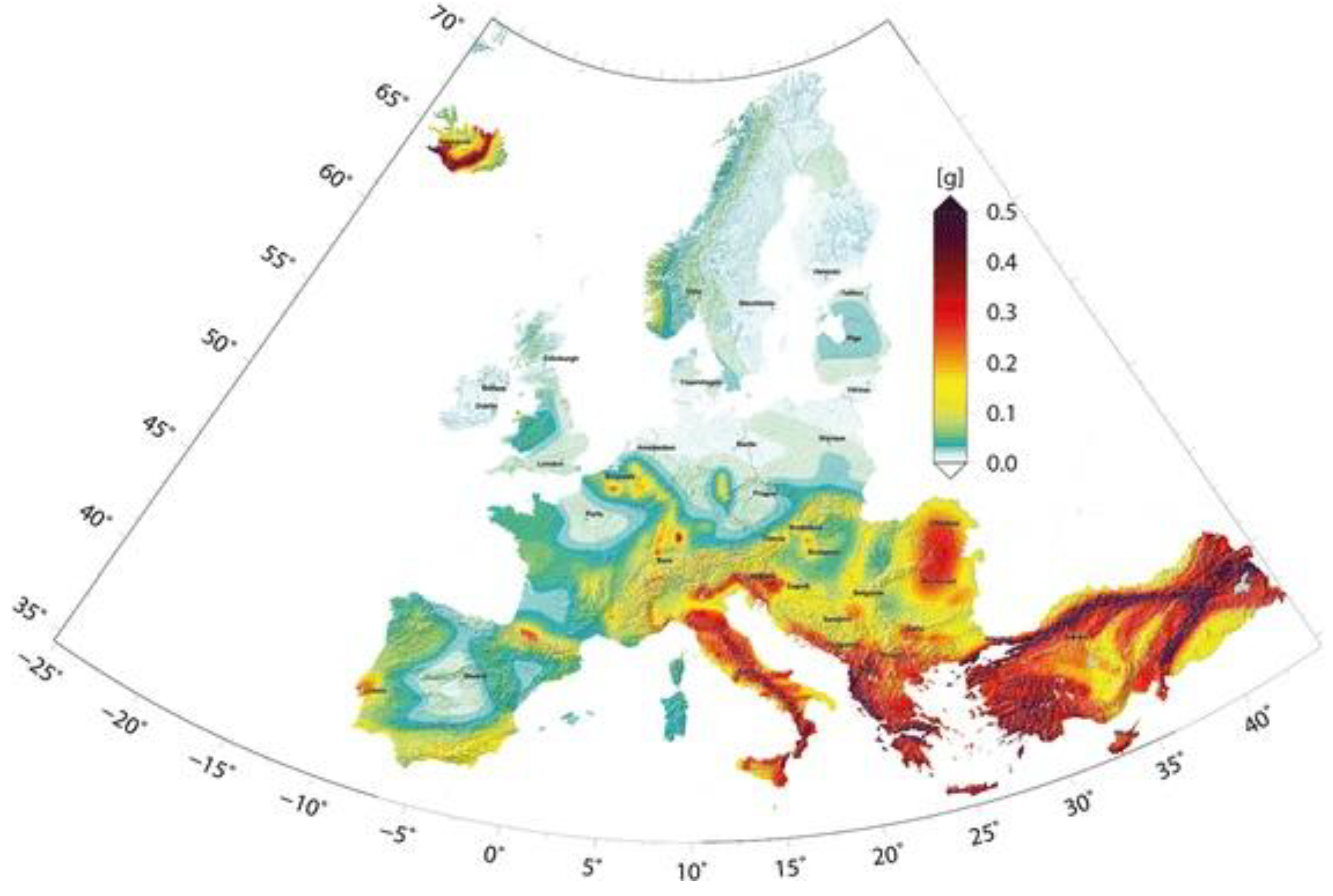
On the other hand, fewer steps forward have been done to reduce the seismic vulnerability of the existing building stock, mostly due to the low percentage of EU countries rated as earthquake-prone (Figure 2). In many European cities, a high percentage of the residential building stock is exposed to seismic risk (around 50% in Italy) [2], and urgently need interventions to improve their seismic safety, i.e., their social sustainability. Regarding the Italian peninsula, the seismicity is due to its geographic position at the border between the Eurasian and African tectonic plates. Their relative movement causes deformations and energy accumulation, which is occasionally released in form of earthquakes. It must be noticed that, in areas with high seismic hazard, the greatest risk is related to human losses and to the damage or collapse of buildings and monuments with great historical and artistic value; these considerations should make structural retrofitting a priority when renovating the building stock.

1.1. The Italian Building Stock and Building Regulations

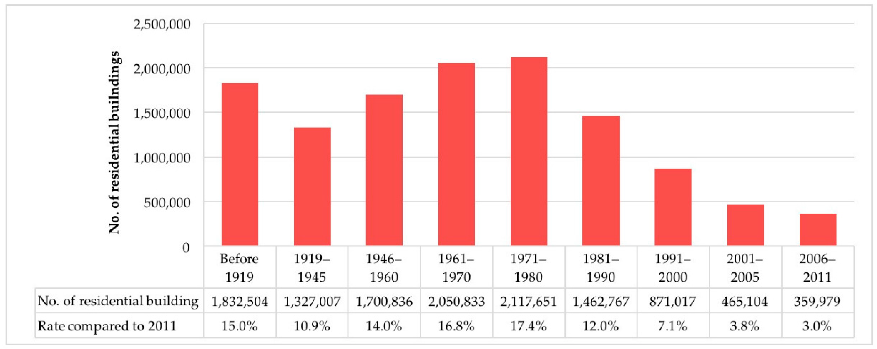
Most of the Italian residential buildings (over 74%) were constructed before 1980 (Figure 3), when only 25% of the national territory was classified as a seismic area. According to the 2011 census of the Italian national statistical institute (ISTAT), around 66% of the existing residential stock was built before 1974, that is to say, before the issue of Law 64/1974, which is the framework law for earthquake-resistant buildings.
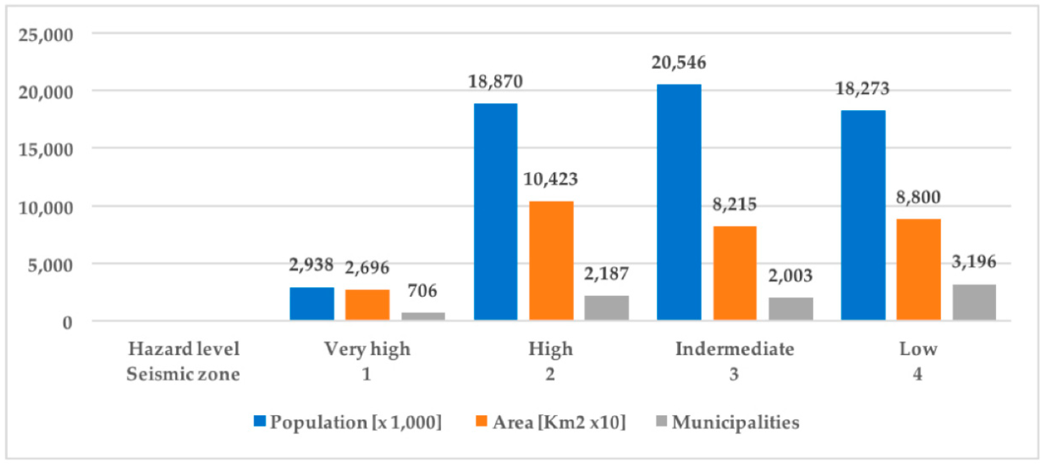
As a matter of fact, this is one of the main reasons of the seismic vulnerability of buildings: in fact, most of them have been designed to sustain gravity loads only, without considering possible seismic forces. Moreover, even those buildings erected after 1974, although in compliance with the laws in force at the time of construction, may not comply with the current seismic regulation because in recent years the seismic hazard map has been updated several times, including a great number of cities in higher risk areas. The areas with a high seismic risk cover 44% of the Italian territory (131 thousand km2) and 36% of the municipalities (2893 units). 21.8 million people live in these areas (36% of the population, in total, 8.6 million families) where there are about 5.5 million residential and non-residential buildings (Figure 4).
Among these, residential buildings correspond to 86%. Furthermore, another risk condition of the existing structures depends on their conservation status. In Italy, nearly 60% of the residential stock was built before 1971 (around 7 million units) and the rest were built in the last 50 years; hence, a large part of the real estate will be in a bad condition, if not renovated.
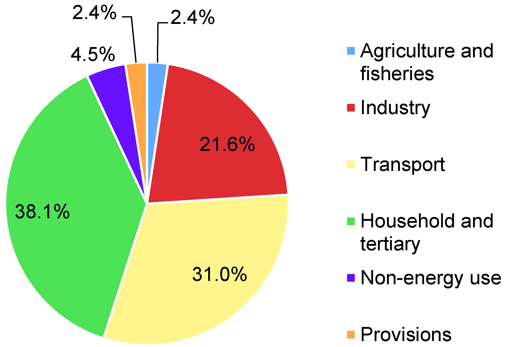
On the other hand, existing buildings are responsible for the consumption of significant amounts of energy and the consequent emission of relevant quantities of greenhouse gases.
The first restrictive Italian regulation concerning the reduction of energy consumption in buildings was Law 10/1991, introduced when around 86% of the current residential building stock had already been built. According to data from BPIE [6], these constructions are characterized by a heating energy demand of about 140–220 kWh m−2 year −1, far beyond the limit enforced by the current regulations [7].
Energy improvements are today mandatory in Italy in case of major renovations. In detail, when refurbishment activities involve more than 25% of the building envelope, the thermal transmittance (U) of the envelope components and the efficiency of the heating and cooling systems must be considerably improved. Besides, if the retrofit involves the entire building envelope, the current regulation imposes the installation of renewable energy sources (RES) systems [8].
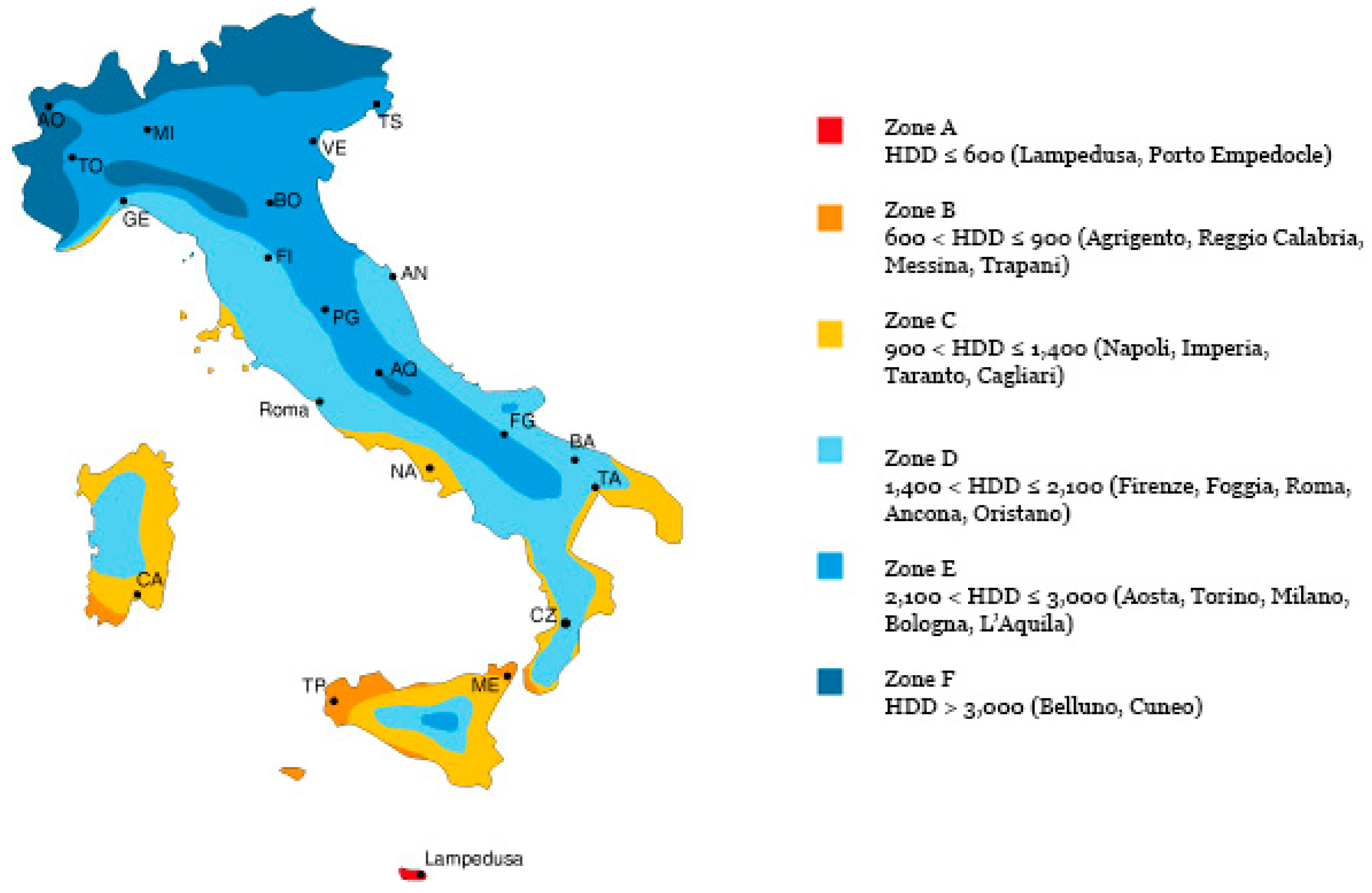
According to the Presidential decree D.P.R. 412/93 [9] and its subsequent modifications, the Italian territory is divided into six different climatic zones, depending on the value of the heating degree-days (HDD). This parameter is computed as the sum, throughout the entire heating season, of the positive differences between the standard indoor temperature and the daily mean outdoor air temperature. For each climatic zone, the current regulation provides various limitations on thermal transmittance of all the components of the building envelope, such as for windows, infill walls, slabs, etc. Moreover, the aforementioned decree states, for each zone, mandatory limitations about the duration of the heating season and the daily number of operations for the heating systems (Table 1). The Italian climatic zoning map is shown in Figure 5.
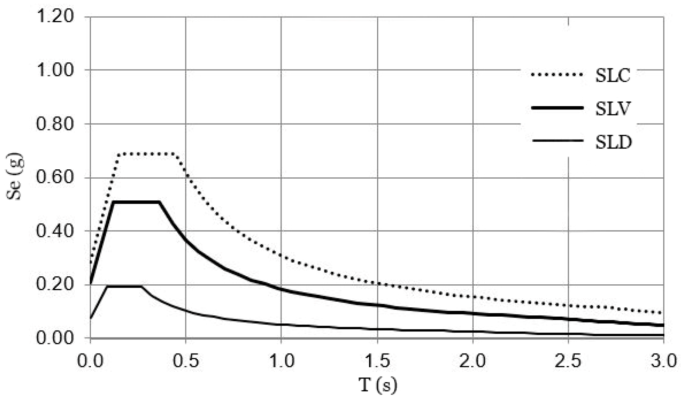
As regards the structural design for earthquake resistance, initially conceived with the sole aim of saving human lives, it has evolved to include other requirements that are imposed on the structures to ensure specific performance for a wide range of seismic events. For this reason, today the philosophy of performance-based design is applied, which provides for various levels of performance or limit states that should be met. In this regard, the Italian code defines the following main limit states:
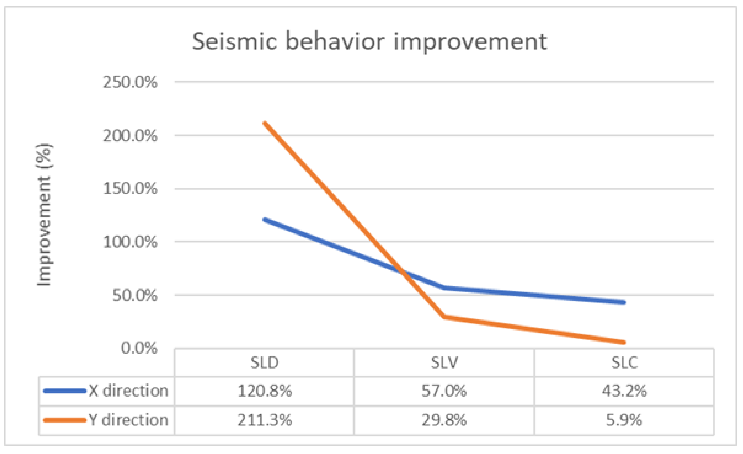
  • Damage limitation limit state (SLD): it is accepted that the non-structural components of the construction suffer damage, but structural members remain basically undamaged and their resistance and stiffness are not compromised;
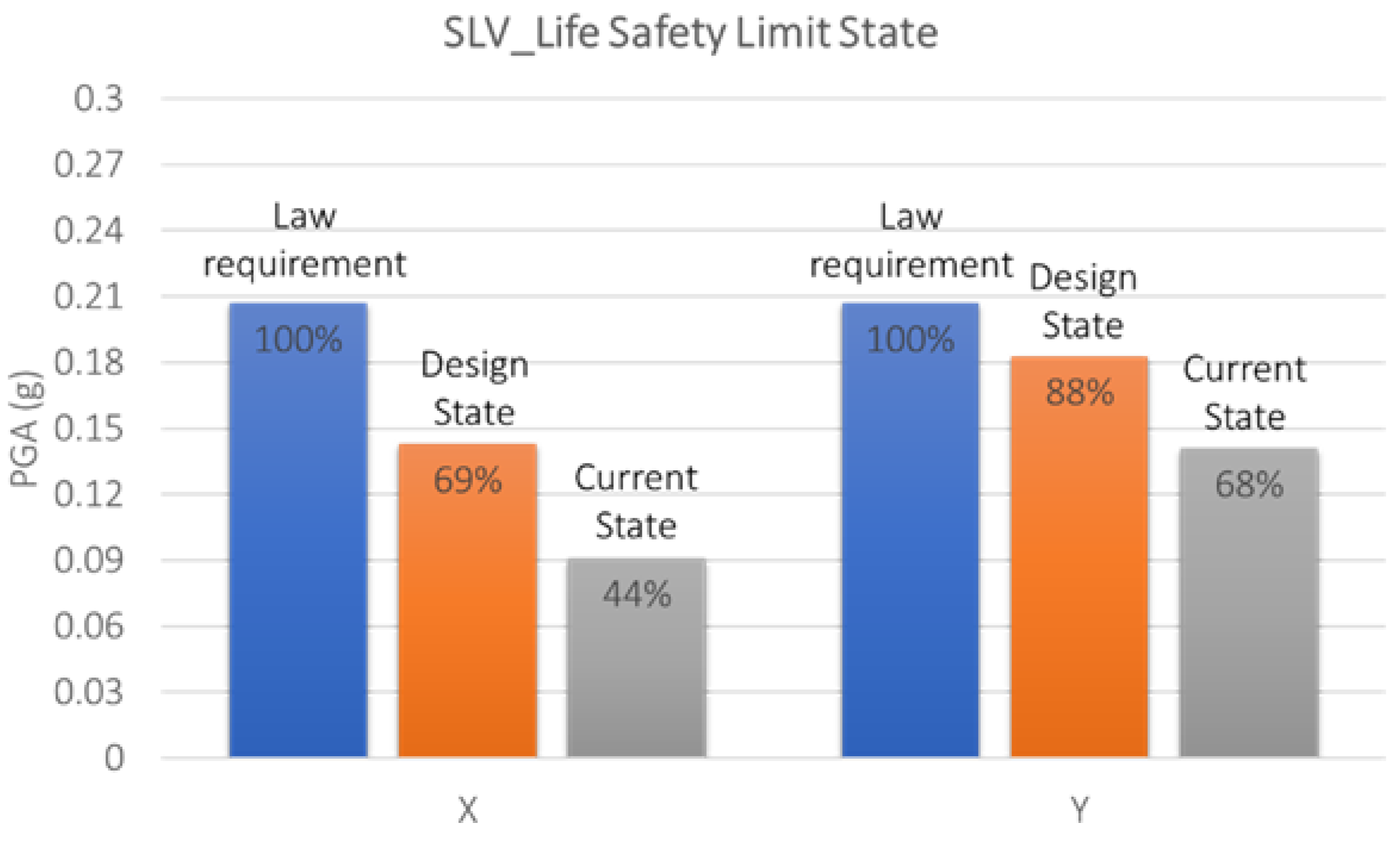
  • Life safety limit state (SLV): heavy damage of non-structural components is admitted, structural members sustain damage also, but a certain resistance and a safety margin for any load is preserved;
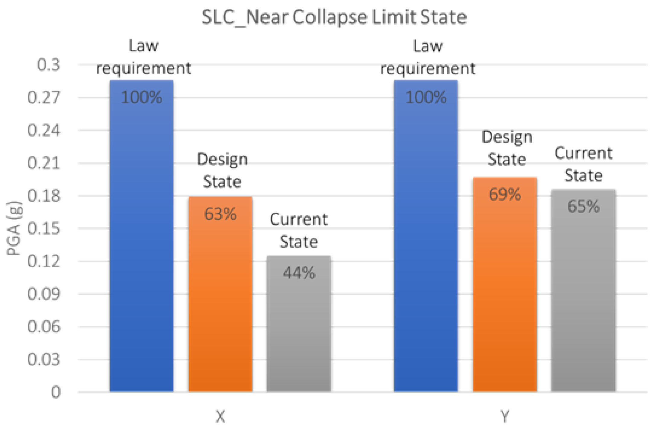
  • Near collapse limit state (SLC): extensive structural damage is allowed, the structure is still capable to sustain gravity loads but the safety margin related to the collapse induced by seismic excitation is minimal.
The legislation stipulates the verification of one or more limit states, considering for each of them an earthquake excitation level with a certain probability of exceedance in a reference period, VR, or the corresponding return period, TR. The reference period is equal to 50 years for residential buildings. The return period, which represents the estimated average time between two seismic events with given earthquake excitation level, is related to the probability of exceedance. Table 2 shows the probabilities of exceedance in VR and the related return periods for VR = 50 years stipulated in the Italian building code for the verifications of the limit states.
The structural project must be carried out with respect to a seismic action which depends essentially on the values of peak ground acceleration (PGA), which is related to seismic zone, type of soil, and topographic surface.

1.2. The Need of an Integrated Retrofitting Approach

Since most buildings are inadequate in terms of both seismic and thermal performance, an integrated renovation approach is strongly recommended. In fact, an integrated approach can provide more benefits at the same time, introducing a sustainable way for retrofitting the existing building stock.
Therefore, the need to define criteria and intervention techniques, aimed at reducing seismic vulnerability and increasing energy efficiency in the context of an integrated approach, is imposed by the social relevance of such a large quantity of buildings with bad energy and seismic performance.
A great advantage deriving from combined actions lies in the possibility of solving two major sustainability issues in a single solution: in fact, one must proceed with the renovation works only once, thus avoiding additional costs and disturbance to the occupants, as occurs in case of distinct and/or unrelated renovation interventions.
Moreover, since the sectoral design takes little account of—or does not consider them at all—other constructive, environmental, and architectural aspects, further emphasis must be put on the fact that the quality of an integrated intervention project can only be higher. As a matter of fact, this would simultaneously solve all those issues, which otherwise would remain disconnected or even conflicting.
Furthermore, an integrated intervention strategy is particularly advantageous because the increase in costs of an eventual maintenance, renovation, or reconstruction following a seismic event would be avoided.
Last but not least, the importance of significantly reducing the risk of post-earthquake emergencies related to people evacuation, as well as the protection of belongings with high economic and/or social value, and above all, the life safeguarding should not be neglected.
From the previous considerations, and considering the high frequency of earthquakes in Italy, the seismic retrofit of the existing building stock is an imperative, since it allows a consistent reduction in the extent of damage, as well as in the number of victims and injured people.
Moreover, one must also consider the opportunity to take advantage of the tax incentives currently in force in Italy [10], which provide an important reduction in the economic burden that owners have to bear to renovate their assets. This is clearly bound to the achievement of certain specific targets in terms of seismic and energy performance. All these tools are even more convenient since the legislator allows the combination of seismic and energy incentives in the case of integrated interventions, achieving the requirements for access to both deductions.
Lastly, a convenient and useful mechanism for the credit assignment has been recently introduced; it allows transferring the tax credit directly to the involved construction companies or to third parties acting as intermediaries in the transaction, reducing the financial outlay for owners.

1.3. The State of Art of Combined Renovation Interventions

To start with a focus on typical strategies for structural retrofit, one possible way is to increase the strength and/or ductility capacity of the structure at a global or local scale. For instance, the global strength of a structure can be increased by adding new seismic-resistant elements, e.g., RC shear walls or steel-braced frames [11]. The new resisting elements should be properly connected to the existing structure and stiff enough to sustain part of the seismic force. Alternatively, the strength can be enhanced locally by interventions on individual structural elements; for example, RC, steel, or fiber reinforced polymer (FRP) jacketing can be used to improve the flexural and/or shear strength of existing RC members [12]. Jacketing is still the most common conventional strengthening technique to increase the strength and ductility of RC members and masonry walls.
Although these techniques are making use of composite materials, they are identical to the conventional RC jacketing. Furthermore, nowadays the use of FRP materials has become very widespread in the design practice for seismic upgrading. FRP has gained increasing popularity within the engineering community, due to its favorable properties such as high strength-to-weight ratio, corrosion resistance, ease and speed of application, and minimal change in the geometry. As reported in [12], despite these advantages, the FRP strengthening technique entails some drawbacks, i.e., poor behavior at high temperatures, inapplicability on wet surfaces or low temperatures, health and safety issues for manual workers, high costs, incompatibility with substrate materials, mainly attributed to the organic resins used to bind and impregnate the fibers. Moreover, when used to strengthen masonry infill walls, FRP strips suffer from brittle failure modes [12,13]. In order to address the problems of the conventional or the FRP strengthening techniques, textile-reinforced mortar has been recently proposed for the seismic retrofitting of RC structures [13]. The use of polymers targeting energy retrofit and structural strengthening was also deeply studied as a retrofit strategy for masonry buildings [14]. Furthermore, the above-mentioned interventions also allow the enhancement of the RC members’ ductility through the confinement of the concrete elements, unlike the solution proposed in this paper, which aims at improving the structural performance mainly by raising strength and stiffness of the infill walls.
An alternative retrofitting solution is to reduce the seismic demand of the structure by base isolation. The isolator inserted beneath the structure elongates the fundamental period of the structure, thus drastically reducing the seismic action onto the structure. This strategy is very effective but it cannot be used when a building is adjoining to other constructions and, in addition, its effectiveness decreases with the aspect ratio, i.e., the height-to-width ratio of the building.
Seismic demand can also be reduced by using dampers [15] (hysteretic, viscous, viscoelastic, etc.), which are devices aimed at dissipating part of the energy provided by the earthquake, thus decreasing the displacement demand of the structure.
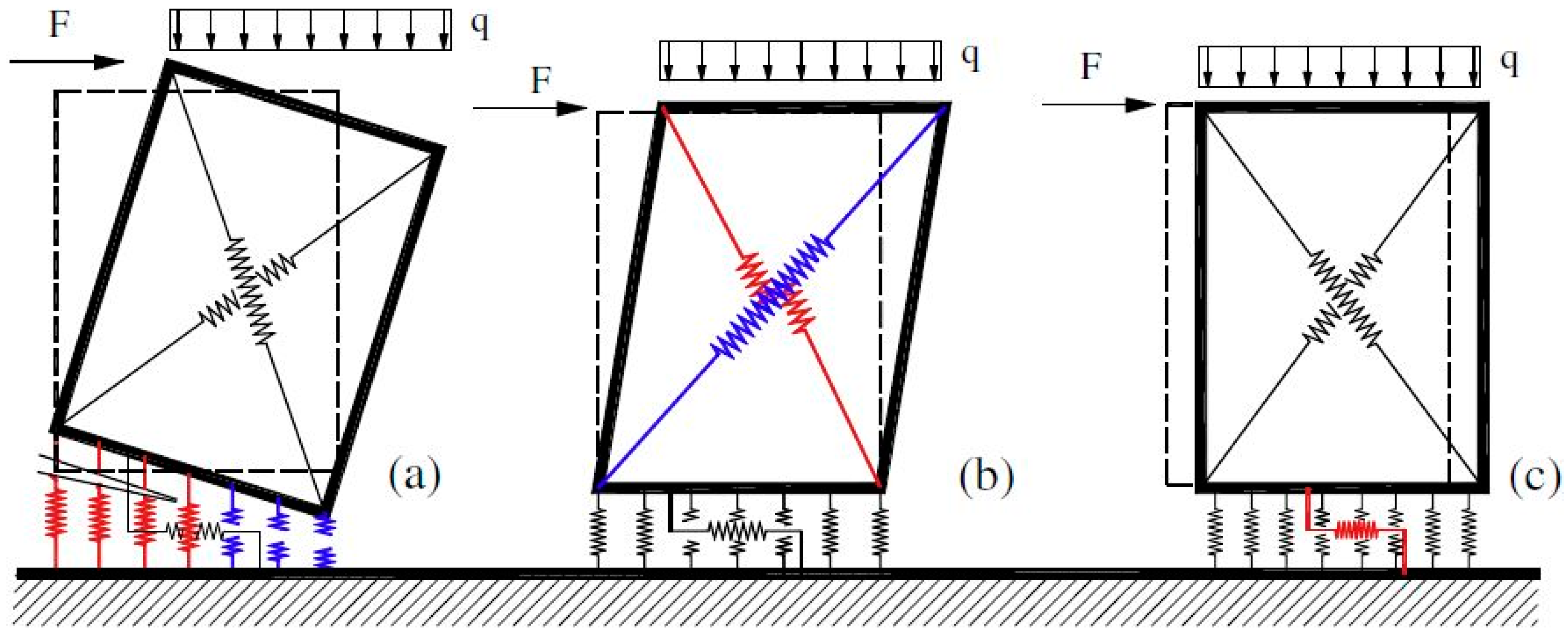
Another route to improve the performance of existing structures and avoid the economic consequences of infill failure is the effort of converting infill walls into a more reliable source of resistance, through a guaranteed and quantifiable contribution to the building’s strength/stiffness.
In the recent past, some researches suggesting an integrated approach to building renovation has been published. Some of them [16,17] proposed to create a double-skin façade to improve both seismic and energy performance. Among all possible global interventions, external interventions are very promising. These interventions do not necessarily require the relocation of the inhabitants during the works; the appropriate use of dampers allows concentrating the damage into limited zone and reducing the repair costs after an earthquake to the substitution of a few elements. In both the aforementioned papers [16,17], an exoskeleton was investigated: the authors proposed a tridimensional addition to the façade of the existing structure able to improve energy performance and structural safety. Furthermore, it also allows an improvement of the architectural image of the building.
In particular, Feroldi et al. analyzed the incidence of the addition of buckling restrained braces to the structure [16], checking the effects related to the increase in stress resulting from the general increase in the system stiffness, with the aim of minimizing damage to the building. Furthermore, in addition to realizing dissipative braces rigidly connected to the existing structure, the possibility to concentrate energy dissipation in the links between the reinforcing building and the external structure is described.
The same strategy suggested by Feroldi et al. has been previously investigated by Manfredi and Masi [17], who also alternatively proposed to replace the external layer of the as-built infill walls with a new panel with better thermal insulation properties (20 cm-thick cored bricks). However, they used a simplified numerical model to take into account the structural contribution of infill walls; in particular, infills are simulated by diagonal strut model and reducing the infill strength and stiffness properties through the Decanini et al. expression [18], in order to consider the presence of openings.
Other studies deepened the concept of the engineered double-skin façade [19], also including energy dissipation systems [20], while D’Urso and Cicero proposed diagrid exoskeletons as a chance to strengthen a structure by means of parametric design [21], mainly trying to achieve the often-neglected beauty of the final output in a usual retrofit design process. The main difference with the present paper is related to the realization of an additional structure that requires a significant quantity of material and additional external space for the installation; however, it should be noted that exoskeletons can be more effective, especially from the structural point of view, making possible the achievement of higher levels of seismic upgrading.
A recent paper by Ferrante et al. [22] suggests an holistic and integrated renovation system based on pre-assembled components. This research is aimed at achieving the highest performances in terms of energy efficiency, as well as safety, social and economic sustainability, by adding a new energy performing envelope and new high-efficient HVAC (heating ventilation air conditioning) systems, using appropriate external addition, again in form of exoskeletons. The application of a new external steel frame connected to the existing RC building enhances the rigidity of the structure with a minimum mass increase, resulting in a reduction in the structure’s fundamental period of vibration.
To sum up, the use of earthquake-resistant exoskeletons entails the increase of the global dimensions of the existing building, while urban regulations often do not allow any extension of the original building footprint. The footprint increase facilitates interventions in very high seismic-prone areas but may imply a derogation from the urban planning parameters [23].
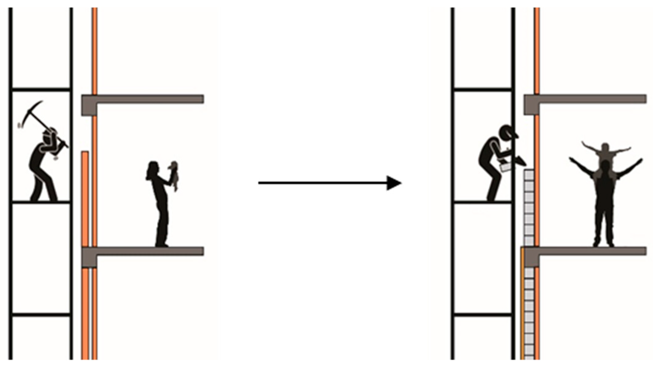
Finally, the proposed solution, described in the following "Section 2.1, may be advantageous compared to the others because it does not entail any derogation to urban regulations. In fact, it can be applied to any structure, even in aggregate ones, unlike the exoskeleton addition. Despite this, the solution with exoskeleton may be interesting for enhancing the architectural image. A similar argument can be made with respect to base isolation systems, which are not applicable in the case of buildings in aggregate and with a high aspect ratio. Proposals that include interventions such as shear walls and steel-braced frames, although among the best for the level of seismic performance achievable, are rather invasive and involve a temporary interruption of the building use. On the other hand, instead, the solution proposed in this study is almost totally applicable from the outside, limiting disturbance to the users. Lastly, the application of a macro-element calculation model to assess the structural behavior of RC-framed buildings with infill walls (see Section 2.4) is more detailed and more precise than the diagonal strut model, as established in [24].

2. Materials and Methods

2.1. A Retrofit Strategy through AAC Blocks Infill Walls

The proposed strategy is based on the replacement of the external layer of double-leaf infill walls with a better-performing AAC blocks panel (see Figure 6).
The proposed solution also comes from the desire to minimize the disruption to the occupants during the renovation works. In fact, by intervening only from the outside, alternate accommodation for occupants can be avoided. Moreover, this solution has advantages both in economic and temporal terms compared to the most common retrofit solutions and, above all, with respect to the usual seismic upgrade. The latter often involves invasive and expensive operations such as the jacketing of structural elements and the addition of RC shear walls, whilst the installation of seismic isolators at the base of buildings is a solution that is sometimes impractical, e.g., when either there is a commercial/residential ground floor or the building is high.
In general, by implementing the proposed solution, the seismic behavior of structures changes, since the new infill panels, interacting with the surrounding RC frame, provide an increase of the stiffness and resistance. However, as a consequence of the lower fundamental period of the structure, higher base shear values will be recorded, thus causing possible excessive stress concentrations on the foundations as well as on the beam–column joints [25].
In more detail, here is a short presentation of the technical features of the material chosen for the blocks: strongly varying according to the chosen model, a block of AAC is characterized by a dry density between 400 and 600 kg m−3, a declared thermal conductivity between 0.100 and 0.150 W m−1 K−1, with higher values corresponding to higher density. The compressive characteristic strength for vertical loads of a block is around 5 Nmm−2, while the compressive characteristic strength of the masonry is about 3.3 Nmm−2. The average and characteristic initial shear strength is 0.43 and 0.30 Nmm−2, respectively.
Because of its low weight, acceptable mechanical resistance, low thermal conductivity, and high fire resistance, AAC is becoming a widespread construction material, being widely used for infill walls of RC-framed buildings. In comparison to traditional infill walls made of hollow or cored bricks, the dynamic response and failure mechanisms might be different.
From the energy point of view, a first series of calculations is performed by considering the mere replacement of the outer layer of clay blocks with the proposed AAC blocks. In particular, the final energy demand for space heating and cooling will be compared based on dynamic energy simulations carried out with Energy Plus v8.4 (U.S. Department of Energy–Building Technologies Office, Washington, DC, USA, 1996). However, in order to further improve the thermal performance of the opaque envelope, reduce the existing thermal bridges, and comply with all the requirements introduced by the most recent regulations, a further layer of thermo-acoustic insulation is considered on the outer side of the walls. In this case, the existing windows will also be replaced with more performing ones, and external-shading systems would be added on the southern fronts.

2.2. The Case Study

The selected apartment block is located in via Santo Cantone in Nesima, a suburb in the west side of the metropolitan city of Catania (Sicily). The main reason for choosing this building is that it is representative of a large part of the Italian residential stock built between the 1950s and 1980s, which now turns out to be obsolete, in accordance with all factors mentioned before.
The building has four stories, with two apartments per story, a sloped roof, and no underground floor. The shape is rectangular, and measures 18.1 m by 11.8 m. The building hosts 8 apartments, with a gross and useful floor area of around 816 and 725 m2, respectively (Figure 7).

2.3. Dynamic Energy Simulations

The energy performance of the selected building was assessed by means of dynamic energy simulations run with EnergyPlus v8.4, by using SketchUp (U.S. Department of Energy–Building Technologies Office, USA, 1996), as graphic interface (Figure 8).
According to the construction techniques adopted in the considered period, double-leaf masonry infill walls are considered, with 8 cm (internal leaf) and 12 cm (external leaf) thick blocks of hollow clay bricks, plus an intermediate 10 cm-thick empty cavity (without insulation). The windows have an aluminum frame without thermal break and single clear glass. An external plastic roller blind is located in front of each window. Both the bottom and the attic floor are formed by a 20 cm thick hollow-core concrete slab with no insulation.
As regards the design state (after retrofit), in a first simulation the outer layer of clay bricks has been replaced by 20-cm commercially available AAC blocks. Their equivalent density and thermal conductivity are, respectively, 500 kg m−3 and 0.15 W m−1 K−1.
Then, a second simulation has been run by adding a 4 cm-thick wooden-fiber external insulation layer (180 kg m−3 and 0.04 W m−1 K−1), and the existing windows have been replaced with wooden-frame double glazing windows. Table 3 reports the U-values of the main envelope components for both current state (before intervention) and design state (after retrofit). The thermal transmittance of the building components is evaluated according to the standard UNI 11300 [5] and UNI 10077 [26].
As reported in the Italian decree 412/1993 [9], Catania is located in the climatic zone B, based on the heating degree days (HDD = 833). The site location is placed respectively at 37.2 and 15.0 degrees of latitude and longitude, with an elevation of 130 m.
Furthermore, other simulation assumptions were made, such as a constant infiltration rate of 0.3 air changes per hour (ACH), accounting for the air leakage through the envelope, and a natural ventilation rate of 2 ACH during daytime (9 am to 6 pm) from the 1st of April to the 30th of September. The main internal heat gains are due to people (100 W per person) and lighting (6 Wm−2), each of them activated in relation to a typical occupancy rate, which was set through an appropriate schedule. Moreover, an ideal heating and cooling system was considered and, in particular, the thermostat was set to 26 °C (in summertime) and 20 °C during the heating season, respectively. Finally, the sensible heating and cooling energy needs are calculated by using the “zone ideal loads” option. The main simulation parameters are summarized in the following Table 4.

2.4. Structural Simulations

As regards the structural point of view, a simulated design was performed. This approach consists in designing a structure according to the building code in force at the time of construction, i.e., the building code in force in Italy in the 1970s in the analyzed case. For this reason, the safety verifications are conducted by the old allowable stress method. The structural standards did not require a design for earthquake resistance. Hence, only vertical loads are taken into account to design the structure [27].
From a quick interpretation it can be noticed that the building seems to have an axis of symmetry, implying an in-plan regularity; it is also quite regular in elevation, thanks to the equalities of the heights of each floor, even though the presence of the stairwell tower constitutes a further element of structural inhomogeneity. In the occurrence of a seismic event, this could entail an irregular structural behavior that, in some cases, can lead to premature and unpredictable collapse mechanisms [28].
In detail, the most commonly used structural materials were chosen, such as concrete of C20/25 class and FeB38k reinforcing bars. The main features of the concrete are summarized in the following Table 5.
The main features of the reinforcing bar steel grade are summarized in the following Table 6.
As a result of the design process, the structure is made up of twenty-six 30 × 30 cm columns, each of those reinforced with four Ø14 steel bars and Ø8 steel stirrups with a spacing of 20 cm. Only regarding the first floor, four of the twenty-six are 40 × 30 cm columns. The concrete slabs are all oriented in the shortest building-length direction (Y) and their three bays lean on two boundary 30 × 50 cm beams and two 100 × 20 cm flat beams. There are no beams in the other direction (Y), except the two boundary 30 × 50 cm beams. The stairs are realized with two jumping concrete slabs and a knee beam for the medium ramp. The carpentry scheme and plan are shown in Figure 9a,b, respectively.
According to the Italian OPCM Ordinance 3519/2006 [29], the construction site (Nesima, Catania) belongs to the seismic zone 2, associated with high hazard levels, since the peak ground acceleration of the earthquake with a 10% probability of exceeding in 50 years is equal to 0.2066 g. The nominal lifetime VN of the structure is equal to 50 years. The topographic condition is T1 type (horizontal terrain or less-than-15° average inclination), while an A-soil type was considered. The spectra prescribed for SLD, SLV, and SLC verifications are shown in Figure 10.
In the given conditions, you can identify fundamental parameters for design and verification phases. Specifically, it should be highlighted that the current legislation provides a PGA of 0.0757 g, 0.207 g, and 0.286 g, respectively, for the limit states SLD, SLV, and SLC.
The characteristics of the infill panels, for both the current state (CS) and the design state (DS), are summed up in the following Table 7.
The seismic performance assessment was carried out using the nonlinear static method of analysis as implemented by the Italian building code (NTC08 [30]) and circular 617/2009 [31]) and Eurocode 8 [32].
The verification process consists of comparing the structural displacement capacity with the displacement demand. The first one is estimated by applying to the structure an appropriate distribution of static forces and increasing them up to the collapse or, more generally, up to the attainment of the limit state considered; the displacement demand is instead identified in the maximum displacement that the structure will be subject to during an earthquake. In order to plot the capacity curve of a structure, representing the relationship between the base shear and the top displacement, you need to perform a nonlinear static analysis.
Generally, you can choose between a model with a concentrated plasticity, a diffused plasticity, or a fiber model. For the former, the formation of plastic hinges concentrated in specific points of the structure is expected (for instance, the end cross sections of members). For the second, each bar is divided into segments with a non-linear moment-curvature bond, while for the fiber model, each segment is further divided into longitudinal strips. In this study, a method of pushover analysis with concentrated plasticity model was applied.
Furthermore, the non-linear static analysis can only be used for buildings whose behavior, under the effect of a considered earthquake, is governed by a mode of main natural vibration characterized by significant mass participation.
The aim of this study is strongly related to the investigation of an integrated seismic and energy renovation approach, considering a recent eligible material as AAC and applying a recently developed modeling method to take infill walls into account in the seismic assessment of RC framed structures with masonry infills. Recently, AAC has been studied by many authors, especially under the boost of its manufacturers, and very satisfactory performance results have been achieved [33,34], making it worthy of further study and applications. On the other hand, the seismic response of the infill walls was simulated by means of a macro-element modeling approach, as described in [35] and [24]: the infill walls are modeled by 2D geometrically consistent equivalent mechanical macro-models capable of simulating the in-plane nonlinear response of unreinforced masonry buildings [36], while the RC frames are modeled by concentrated-plasticity beam–column elements. In particular, the infill wall is modeled as a plane discrete element, with a quadrilateral shape, with rigid edges connected by four hinges and two diagonal nonlinear springs. Through this simple and realistic mechanical simulation, three main failure mechanisms can occur: the flexural, the diagonal-shear, and shear-sliding failure mode (Figure 11).
The software used for the structural modeling is 3DMacro [37], implemented according to the previously described approach by a group of researchers of the University of Catania.

3. Results and Discussions

3.1. Structural Performance

Pushover analyses, both from Group 1 (main distributions, forces proportional to mass) and Group 2 (secondary distributions, forces proportional to mass and height), were performed in both X (longitudinal) and Y (transversal) directions and with either positive (+) or negative (-) sign of the horizontal forces. In this way, for each limit state considered, eight capacity curves of the structure were determined. For each pushover analysis, the PGA corresponding to the attainment of the considered limit state is determined. The smallest out of the eight PGA values represents the PGA that leads the structure to the considered limit state, i.e., the PGA capacity of the structure. The ratio of the value thus obtained (from now onwards called PGAC), for both the CS and DS, to the PGA value stipulated in the code for the verification of the considered limit state provides the PGA capacity of the structure as a percentage of that stipulated in the code (code requirement).
Generally, it can be said that the proposed intervention involves a considerable improvement of the seismic response and, therefore, an increase of the safety level. In order to make a comparison between ex-ante and ex-post, first of all, the performances at the several limit states must be compared.
Starting from the damage limitation limit state (SLD), the proposed intervention involves the highest improvement over other performance levels. As can be seen from Figure 12, showing the PGA values when the direction changes in the considered cases, along the X direction, the PGA capacity of 0.0192 g is elevated to 0.0424 g, more than doubling (120.8%) the value of the capacity related to the achievement of the SLD. Nevertheless, this value still keeps below that required by the regulations in Nesima, Catania (0.0757 g). On the other hand, if one observes the PGA value for which the limit state is reached along the Y direction, it is evident that the upgraded structure entails an improvement (211.3%) that satisfies the regulatory requirements.
Regarding the SLV, there is also an improvement, although of smaller entity: in fact, the PGA that leads to the limit state reached a 57% increase, from 0.0911 g to 0.143 g (Figure 13). In this way, it is possible to satisfy about 70% of the regulatory request, thus not achieving a full seismic upgrading, but nevertheless guaranteeing higher levels of safety in the event of earthquake. Furthermore, a less dissimilar behavior is observed between X and Y directions.
As regards the near collapse limit state (SLC), the slightest improvement is recorded: indeed, the PGA that leads the structure to SLC is higher by about 43.2%, passing from 0.125 g to 0.179 g. In this way, it is possible to satisfy about 63% of the regulatory request, certainly more than before retrofit (44%), but not high enough for the full seismic upgrading. Moreover, the structural behavior in the two X and Y directions is nearly the same, according to the PGA equal to 0.179 g and 0.197 g, respectively (Figure 14).
As already mentioned, the structural behavior in the case of seismic stress is generally increased, with different relevance depending on the direction and the considered limit state.
A first consideration can be made by comparing the percentage increase of the of the PGAC of the building in DS with respect to that of the CS; from the latter parameter, the seismic behavior improvement brought by the proposed solution was evaluated, for each direction and for each considered limit state. Passing from the SLD to the SLC limit state, a decreasing trend of the intervention effectiveness is recorded. This is due to the fact that the new infill panel guarantees better performance compared to the existing one, until it reaches a state of damage such that the difference with the actual state is reduced more and more (see Figure 15).
Another important remark is connected to the different improvement in X and Y directions, especially for SLD, where a significant improvement has been recorded in Y direction. It should be remembered that, in Y direction, the infill walls have a very low percentage of openings (less than 5%); for this reason, in fact, the building is particularly more resistant to horizontal actions in this direction.
In conclusion, this intervention improves the safety and, more generally, the seismic performance of the building. However, in spite of the significant economic burden, it may not achieve a full seismic upgrade, especially in the case of strong ground motions and when infills present large openings (case of the X direction in the examined building). According to the results, complementary interventions devoted to increase the ductility of the structure and/or to reduce its seismic demand are also recommended.

3.2. Energy Performance

A first interesting result, concerning the thermal performance of the proposed retrofit solution, regards its stationary and dynamic thermal parameters.
Table 8 shows the comparison between the current wall configuration and the case where the outer layer of clay bricks is replaced by 20-cm commercially available AAC blocks. Together with the U-values, the comparison is made in terms of time shift and periodic thermal transmittance. Under the assumption of a cyclic temperature excitation acting on the outer side of the wall, the time shift φ is the time lag between the peak outside temperature and the peak heat flux transferred indoors; accordingly, the phase shift is measured in hours. Walls with good dynamic thermal performance should have a high phase shift (φ > 10 h). On the other hand, the periodic thermal transmittance YIE is the ratio between the amplitude of the two cyclic functions describing the heat flux and the temperature excitation, respectively. A recent national regulation states that external walls in new or renovated buildings must have YIE < 0.10 W m−2 K−1.
The calculation of these dynamic parameters involves the use of complex numbers, and has been performed according to the algorithms reported in ISO Standard 13786 [38]. As shown in Table 8, the only replacement of the existing outer infill panels with the AAC blocks reduces the U-value—hence the heat losses—by 50%. The time shift increases by 4 h, and now reaches a good performance level (φ > 10 h); the periodic thermal transmittance is also considerably reduced and approaches the maximum value allowed by Italian regulations. However, as described in Section 2.1, the values reported in Table 8. do not fully comply with the recent Italian regulations, hence a further addition of an outer insulation layer is considered afterwards.
The main results of the dynamic energy simulations are reported in Figure 15. As a result of the final renovation solution, significant reductions in the energy demand for heating and cooling are observed, although for the latter, in the intermediate floors, savings are less substantial. Specifically, the total energy needs are reduced by 38% and 27% for heating and cooling (see Figure 16), respectively, with important consequences also on the reduction of greenhouse gas emissions. Moreover, after the proposed retrofit, the average heating and cooling needs for unit net useful surface are, respectively, 21.5 kWh m−2 year −1 and 9.3 kWh m−2 year −1.
By looking in more detail at the behavior of the different floors, different trends emerge. In fact, as regards heating, the savings stood at 36%, 52%, and 22%, respectively, for the lower, intermediate, and upper stories, as shown in Figure 16. This trend can be justified by the greater impact of the external wall insulation. On the other hand, as regards summer cooling, the trend is reversed, that is, minimum savings are observed in the intermediate level (8.9%), while on the ground floor and the upper story there is a higher saving percentage: respectively, 75% and 27% (Figure 17).
The plots do not show the results for the only replacement of the AAC blocks, which is not sufficient to comply with national regulations in Italy. However, it is worth underlining that this intervention alone would reduce the heating needs by 11%, 14%, and 5%, for the lower, intermediate, and upper stories, respectively. The savings in the cooling needs, instead, would amount to 10%, 1%, and 4%. This suggests that the replacement of the only external clay blocks implies good improvements.
Finally, as an alternative to the solution described above, it would also be possible to apply a thermo-acoustic insulating material with greater thickness (6 cm instead of 4 cm) to the infill walls. With this configuration, which is undoubtedly more suitable in other latitudes (e.g., Northern Europe), greater savings are achieved for winter air-conditioning, but a non-negligible increase in the summer needs is recorded. Therefore, it can be concluded that the adoption of 4 cm of external insulation is more appropriate for the case study, being located in a city where the summer season is particularly demanding.

4. Conclusions

This paper proposes an integrated seismic and energy retrofitting approach for RC-framed buildings. This approach is based on the replacement of the external layer of double-leaf infill walls with a better performing panel made of autoclaved aerated concrete (AAC) blocks.
This solution enhances the seismic and energy performance of the renovated building and provides a reduced disruption to the occupants during retrofitting works, since it allows intervening mainly from the outside of the building. The proposed strategy decreases the number of potential injured and deaths resulting from an earthquake and reduces the damages and the consequent economic efforts related to repairs and reconstructions, contributing to enhancing the safety and social sustainability of our cities, adapting them to hazardous events.
From a structural point of view, the proposed intervention involves the highest improvement (211.3%) with reference to the performance objective related to the SLD, where the PGA corresponding to the attainment of the limit state increases from 0.0283 g to 0.0881 g. Improvements of minor relevance are recorded at SLV and SLC, with an increase in PGA values up to 57% and 43%, respectively.
On the other hand, this intervention provides a significant reduction in the energy demand for space heating and cooling. Actually, the only replacement of the external clay bricks with the AAC blocks reduce, on average, the heating and cooling needs by 10% and 4%, respectively. Moreover, both the U-values and the dynamic thermal properties (time shift, periodic thermal transmittance) of the walls are greatly improved, thanks to the low thermal conductivity and the thermal mass of the AAC blocks. However, this is not sufficient to comply with all requirements of the most recent national regulations in Italy: hence, a further additional outer insulation layer of 4 cm is needed. Under this further configuration, the overall achievable savings correspond to 9388 kWh and 2488 kWh per year for heating and cooling, respectively, corresponding to a reduction by 38% and 27%,
In conclusion, the results obtained are particularly interesting given the wide range of RC framed buildings that could be renovated by applying the proposed integrated strategy, the limitation of occupants’ disruption, and the opportunity of achieving a better architectural image. Furthermore, the proposed strategy increases the property value and the building life-cycle, decreases the energy bill, and may have a further positive psychological fallout on the building users, as a result of the higher safety and comfort. A significant structural improvement can be achieved by the proposed intervention. However, although it requires a significant economic effort, a full seismic upgrade of the building is unlikely to be achieved in high seismicity areas. In this case, further interventions are required to increase the ductility of the structure and/or to reduce the seismic demand of the building. The combination of the retrofit by AAC block infills with other available or novel seismic upgrading techniques will be a matter of future developments of the research.

Author Contributions

Conceptualization, A.A. and G.M.; software, A.A.; supervision, G.E., G.M. and E.M.M.; writing—original draft, A.A.; writing—review and editing, G.E., G.M. and E.M.M.

Funding

This work has been partially funded by the University of Catania within the PON 2014–2020 project “eWas—An early warning system for cultural heritage”.

Acknowledgments

The authors would like to thank Gruppo Sismica for providing a temporary license for the structural modelling software 3DMacro.

Conflicts of Interest

The authors declare no conflict of interest. The funders had no role in the design of the study; in the collection, analyses, or interpretation of data; in the writing of the manuscript, or in the decision to publish the results.

References

  1. Ministry of Economic Development. Bilancio Energetico Nazionale 2017; Economico, M.D.S., Ed.; Ministry of Economic Development: Roma, Italy, 2016. [Google Scholar]
  2. La Greca, P.; Margani, G. Seismic and energy renovation method for sustainable cities. Sustainability 2018, 10, 254. [Google Scholar] [CrossRef]
  3. Woessner, J.; Laurentiu, D.; Giardini, D.; Crowley, H.; Cotton, F.; Grünthal, G.; Valensise, G.; Arvidsson, R.; Basili, R.; Demircioglu, M.B.; et al. The 2013 European Seismic Hazard Model: Key components and results. Bull. Earthq. Eng. 2015, 13, 3553–3596. [Google Scholar] [CrossRef]
  4. BPIE. Europe’s Buildings under the Microscope. A Country-By-Country Review of the Energy Performance of Buildings; Buildings Performance Institute Europe: Brussels, Belgium, 2011. [Google Scholar]
  5. Ente nazionale italiano di unificazione. Prestazioni Energetiche Degli Edifici Parte 1: Determinazione del Fabbisogno di Energia Termica Dell’edificio per la Climatizzazione Estiva ed Invernale. In UNI/TS 11300-1; UNI: Roma, Italy, 2014. [Google Scholar]
  6. Ministry of Economic Development. Applicazione Delle Metodologie di Calcolo Delle Prestazioni Energetiche e Definizione Delle Prescrizioni e dei Requisiti Minimi Degli Edifici; Minimum Requirements Decree, June 26, 2015; Ministry of Economic Development: Roma, Italy, 2015. [Google Scholar]
  7. Ente nazionale italiano di unificazione. Prestazioni Energetiche Degli Edifici Parte 2: Determinazione del Fabbisogno di Energia Primaria e Dei Rendimenti per la Climatizzazione Invernale, per la Produzione di Acqua Calda Sanitaria, per la Ventilazione e per L’illuminazione. In UNI/TS 11300-2; UNI: Roma, Italy, 2019. [Google Scholar]
  8. Ministry of Economic Development. Adeguamento Linee Guida Nazionali per la Certificazione Energetica Degli Edifici. In Allegato 1; Inter-Ministerial Decree 26 June, 2015; Gazzetta Ufficiale della Repubblica Italiana: Roma, Italy, 2015. [Google Scholar]
  9. Presidential Decree. In D.P.R. 412; Gazzetta Ufficiale della Repubblica Italiana: Roma, Italy, 1993.
  10. Legge di Bilancio 2019. In Law 145; Gazzetta Ufficiale della Repubblica Italiana: Roma, Italy, 2018.
  11. Georgescu, E.S.; Georgescu, M.S.; Macri, Z.; Marino, E.M.; Margani, G.; Meita, V.; Cascone, S.M.; Petran, H.; Rossi, P.P.; Sapienza, V.; et al. Seismic and Energy Renovation: A Review of the Code Requirements and Solutions in Italy and Romania. Sustainability 2018, 10, 1561. [Google Scholar] [CrossRef]
  12. Bournas, D.A. Concurrent seismic and energy retrotting of RC and masonry building envelopes using inorganic textile-based composites combined with insulation materials: A new concept. Compos. Part B Eng. 2018, 148, 166–179. [Google Scholar] [CrossRef]
  13. Bournas, D. Innovative Materials for Seismic and Energy Retrofitting of the Existing EU Buildings; Publications Office of the European Union: Luxembourg, 2018. [Google Scholar]
  14. Sassu, M.; Stochino, F.; Mistretta, F. Assessment Method for Combined Structural and Energy Retrofitting in Masonry Buildings. Buildings 2017, 7, 71. [Google Scholar] [CrossRef]
  15. Christopoulos, C.; Filiatrault, A. Principles of Passive Supplemental Damping and Seismic Isolation; IUSS Press: Pavia, Italy, 2006. [Google Scholar]
  16. Feroldi, F.; Marini, A.; Belleri, A.; Passoni, C.; Riva, P.; Preti, M.; Giuriani, E.; Plizzari, G. Sustainable seismic retrofit of modern RC buildings through an integrated structural, energetic and architectural approach adopting external engineered double skin façades. Progett. Sismica 2014, 5, 31–47. [Google Scholar]
  17. Manfredi, V.; Masi, A. Seismic strengthening and energy efficiency: Towards an integrated approach for the rehabilitation of existing RC buildings. Buildings 2018, 8, 36. [Google Scholar] [CrossRef]
  18. Decanini, L.; Liberatore, L.; Mollaioli, F. Strength and stiffness reduction factors for infilled frames with openings. Earthq. Eng. Eng. Vib. 2014, 13, 437–454. [Google Scholar] [CrossRef]
  19. Marini, A.; Passoni, C.; Belleri, A.; Feroldi, F.; Preti, M.; Metelli, G.; Riva, P.; Giuriani, E.; Plizzari, G. Combining seismic retrofit with energy refurbishment for the sustainable renovation of RC buildings: A proof of concept. Eur. J. Environ. Civ. Eng. 2017, 21, 1–22. [Google Scholar] [CrossRef]
  20. Takeuchi, T.; Yasuda, K.; Iwata, M. Seismic retrofitting using energy dissipation façades. In Proceedings of the ATC-SEI09, San Francisco, CA, USA, 10–12 September 2009. [Google Scholar]
  21. D'Urso, S.; Cicero, B. From the Efficiency of Nature to Parametric Design. A Holistic Approach for Sustainable Building Renovation in Seismic Region. Sustainability 2019, 11, 1227. [Google Scholar] [CrossRef]
  22. Ferrante, A.; Mochi, G.; Predari, G.; Badini, L.; Fotopoulou, A.; Gulli, R.; Semprini, G. A European Project for Safer and Energy Efficient Buildings: Pro-GET-One (Proactive Synergy of inteGrated Efficient Technologies on Buildings’Envelopes. Sustainability 2018, 10, 812. [Google Scholar] [CrossRef]
  23. Marini, A.; Passoni, C.; Riva, P.; Negro, P.; Romano, E.; Taucer, F. Technology Options for Earthquake Resistant, Eco-Efficient Buildings in Europe: Research Needs; Publications Office of the European Union: Luxembourg, 2014. [Google Scholar]
  24. Pantò, B.; Caliò, I.; Lourenço, P.B. Seismic safety evaluation of reinforced concrete masonry infilled frames using macro modelling approach. Bull. Earthq. Eng. 2017, 15, 3871–3895. [Google Scholar] [CrossRef]
  25. Fiore, A.; Mezzina, M.; Porco, F.; Uva, G. Solidarizzazione delle tamponature per il miglioramento sismico di edifici esistenti. In Proceedings of the L’ingegneria sismica in Italia, Padova, Italy, 30 June–4 July 2013. [Google Scholar]
  26. Ente nazionale italiano di unificazione. Prestazione Termica di Finestre, Porte e Chiusure Oscuranti–Calcolo Della Trasmittanza Termica. In UNI 10077-1; UNI: Roma, Italy, 2018. [Google Scholar]
  27. Ghersi, A. Il Cemento Armato; Dario Flaccovio Editore: Palermo, Italy, 2010. [Google Scholar]
  28. Ghersi, A.; Lenza, P. Edifici Antisismici in Cemento Armato; Dario Flaccovio Editore: Palermo, Italy, 2017. [Google Scholar]
  29. Italian Civil Protection Agency. Criteri Generali per L’individuazione Delle Zone Sismiche e per la Formazione e L’aggiornamento Degli Elenchi Delle Medesime Zone. In Ordinance OPCM N 3519; Gazzetta Ufficiale della Repubblica Italiana: Roma, Italy, 2006. [Google Scholar]
  30. Ministry of Transport and Infrastructures. Norme Tecniche per le Costruzioni–NTC08. In Ministrial Decree 14 January 2008; Gazzetta Ufficiale della Repubblica Italiana: Roma, Italy, 2008. [Google Scholar]
  31. Consiglio Superiore dei LL.PP. Instructions for Applying the NTC08 Code. In Circular 617; Gazzetta Ufficiale della Repubblica Italiana: Roma, Italy, 2009. [Google Scholar]
  32. BSI. Eurocode 8: Design of Structures for Earthquake Resistance. In EN 1998-1; European Committee for Standardization (CEN): Brussels, Belgium, 2004. [Google Scholar]
  33. Rosti, A.; Penna, A.; Rota, M.; Magenes, G. In-plane cyclic response of low-density AAC URM walls. Mater. Struct. 2016, 49, 4785–4798. [Google Scholar] [CrossRef]
  34. Tomazevic, M.; Gams, M. Shaking table study and modelling of seismic behavior of confined AAC masonry buildings. Bull. Earthq. Eng. 2012, 10, 863–893. [Google Scholar] [CrossRef]
  35. Caliò, I.; Pantò, B. A macro-element modelling approach of Infilled Frame Structures. Comput. Struct. 2014, 143, 91–107. [Google Scholar] [CrossRef]
  36. Caliò, I.; Marletta, M.; Pantò, B. A new discrete element model for the evaluation of the seismic behaviour of unreinforced masonry buildings. Eng. Struct. 2012, 40, 327–338. [Google Scholar] [CrossRef]
  37. Gruppo Sismica s.r.l. 3DMacro: Software for Masonry Buildings; Gruppo Sismica: Catania, Italy, 2009. [Google Scholar]
  38. International Organization for Standardization. Thermal performance of building components–Dynamic thermal characteristics–Calculation methods. In ISO 13786; ISO: Geneva, Switzerland, 2017. [Google Scholar]
Figure 1. Final energy consumption by sector in Italy [1].
Sustainability 11 03939 g001
Figure 2. ESHM13 map of peak ground acceleration (PGA) for 10% probability of exceedance in 50 years in units of standard gravity (g) for reference rock soil (vs30 = 800 m/s). This corresponds to PGA values that return on average every 475 years [3].
Sustainability 11 03939 g002
Figure 3. Historical growth of the residential building stock [4].
Sustainability 11 03939 g003
Figure 4. Distribution of population, area, and municipalities by seismic zone [5].
Sustainability 11 03939 g004
Figure 5. Climatic zoning in Italy.
Sustainability 11 03939 g005
Figure 6. Infographic of the proposed strategy.
Sustainability 11 03939 g006
Figure 7. Plan of an intermediate floor (all floors have the same plan).
Sustainability 11 03939 g007
Figure 8. 3D view of the model used for building energy simulation.
Sustainability 11 03939 g008
Figure 9. (a) Floor slab scheme; (b) Carpentry plan.
Sustainability 11 03939 g009
Figure 10. Elastic spectra in Nesima (CT) for A-soil and T1-topographic condition.
Sustainability 11 03939 g010
Figure 11. Simulation of Flexural (a), diagonal-shear (b), and shear-sliding (c) failure mechanisms [35].
Sustainability 11 03939 g011
Figure 12. PGA comparison (requirement, CS and DS), for both directions, for SLD.
Sustainability 11 03939 g012
Figure 13. PGA comparison (requirement, CS and DS), for both directions, for SLV.
Sustainability 11 03939 g013
Figure 14. PGA comparison (requirement, CS and DS), for both directions, for SLC.
Sustainability 11 03939 g014
Figure 15. Seismic behavior improvement in relation to the limit state and to the seismic direction.
Sustainability 11 03939 g015
Figure 16. Heating and cooling energy needs per unit net surface (CS and DS).
Sustainability 11 03939 g016
Figure 17. Percentage of energy savings per storey.
Sustainability 11 03939 g017
Table 1. Climatic zones in relation to degree-days.
Climatic ZoneDegree-Days (HDD)Heating SeasonHours per Day Limit
AHDD ≤ 6001st December–15th March6 hours a day
B600 < HDD ≤ 9001st December–31st March8 hours a day
C900 < HDD ≤ 1.40015th November–31st March10 hours a day
D1.400 < HDD ≤ 2.1001st November–15th April12 hours a day
E2.100 < HDD ≤ 3.00015th October–15th April14 hours a day
FHDD > 3.000whole yearno limitation
Table 2. Probability of exceeding and return period according to NTC18.
Limit StateProbability of Exceeding in the Reference Period (VR)Return Period (VR = 50 years)
SLD63%50
SLV10%475
SLC5%975
Table 3. U-values of the enveloped components before and after renovation.
Building ComponentCurrent StateU-Value (W m−2 K−1)Design StateU-Value (W m−2 K−1)
External infill wallDouble leaf of bricks1.11Layers of bricks, AAC, insulation0.343
Internal floorHollow-core concrete slab1.83--
Attic floorHollow-core concrete slab2.03Insulated concrete slab0.286
WindowsAluminum, float glass5.98Wood frame – double glazing1.77
Table 4. Main parameters of the energy simulation.
Main Simulation ParametersValueUnit
Air infiltration rate0.3ACH
Ventilation rate2ACH
Occupancy rate0.044People for m2
People sensible heat load100W for person
Artificial lights load4W m−2
Table 5. Concrete C 20/25 features.
Concretefck [MPa]fctk [MPa]εc2 [%]εcu [%]σadm [MPa]E [MPa]
C 20/25201.550.20.358.530000
Table 6. Steel FeB38k features.
Steel Barsfyk [MPa]fuk [MPa]εykσadm [MPa]E [MPa]
FeB38k3754500.00188215200,000
Table 7. Mechanical characteristics of masonry infill: Current State (CS) and Design State (DS).
Mechanical Characteristics of Masonry InfillCurrent State (Clay Hollow Bricks)Design State (AAC blocks)
Young Modulus E [MPa]12003000
Shear Modulus G [MPa]7001200
Compressive stress fm [MPa]1.25.35
Shear stress τ0 [MPa]0.070.38
Specific weight w [kN m−3]86.6
Table 8. Effect of the AAC blocks in terms of stationary and dynamic thermal performance.
Current StateWith AAC Blocks
U-value [W m−2 K−1]1.110.52
YIE [W m−2 K−1]0.620.16
Time shift, φ [h]7.010.9

