Design Parameters for the Early Development Phase of Battery Electric Vehicles

 ,
,  , and
, and
Abstract
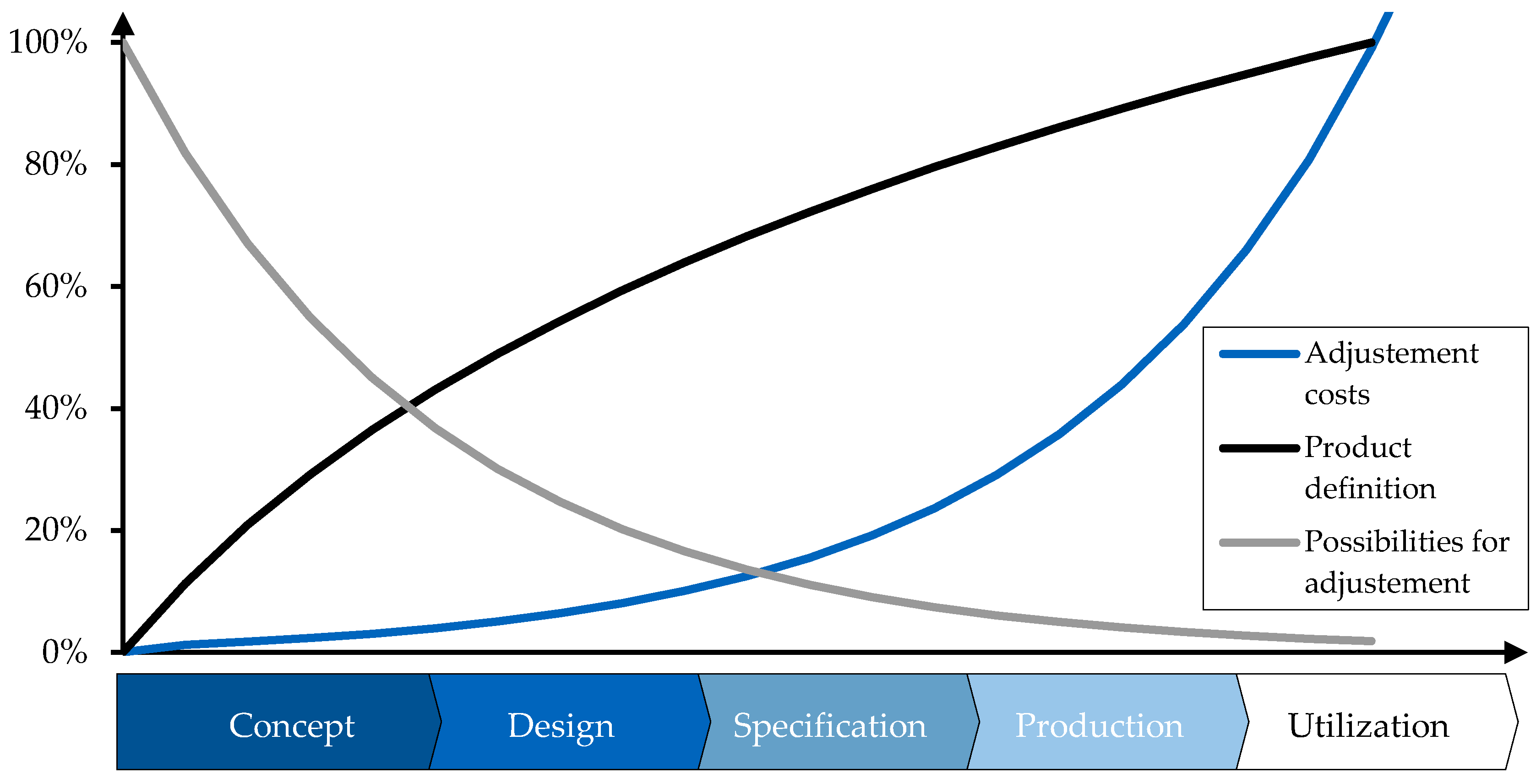
:1. Introduction
2. BEV Architecture Definition and Identification of the Relevant Authors
2.1. Vehicle Architecture
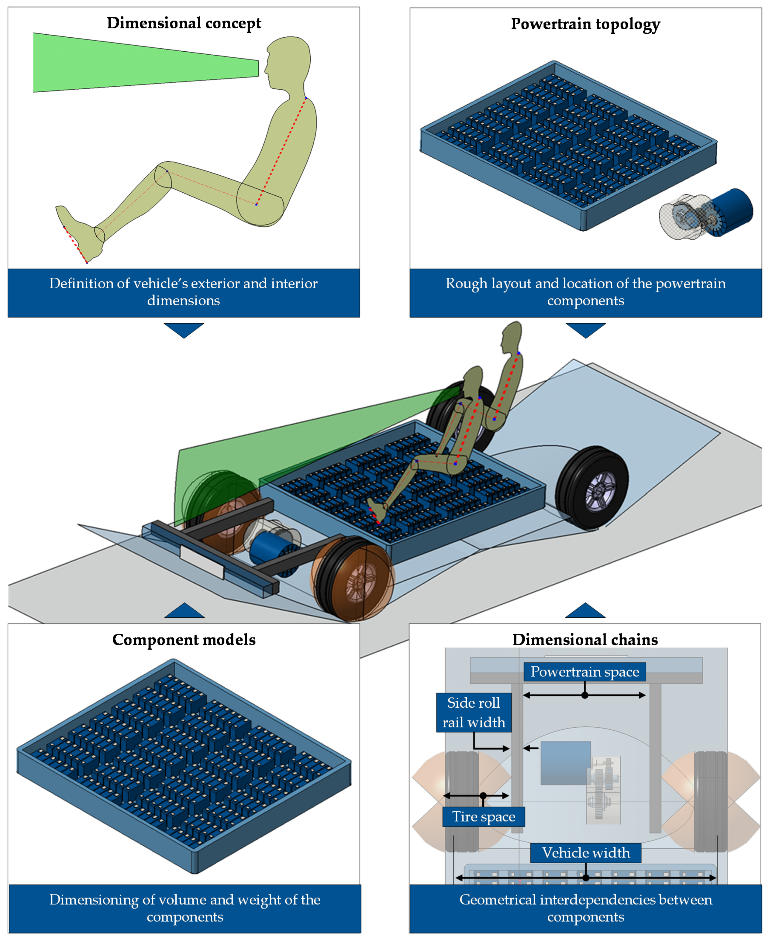
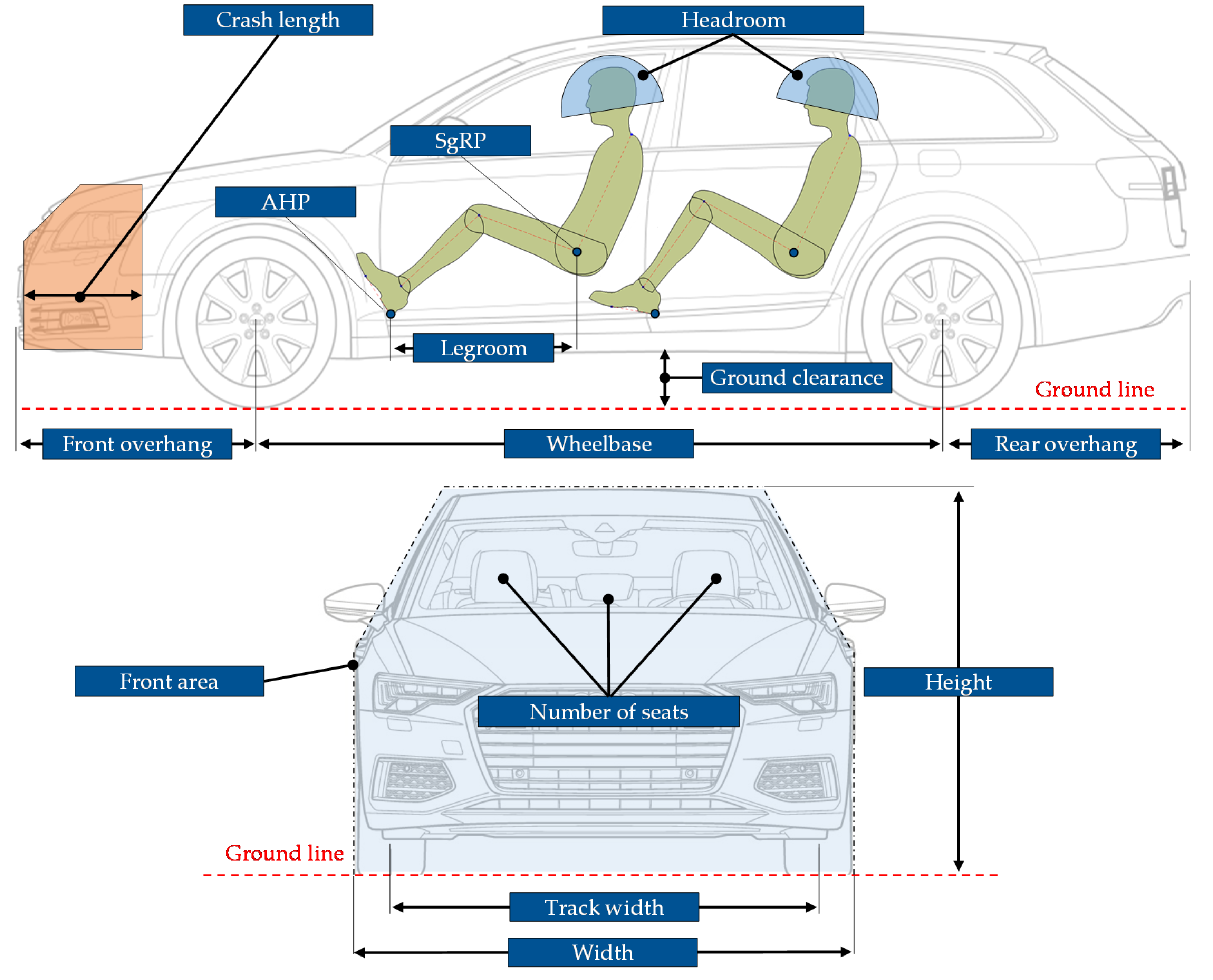
- Dimensional concept: The dimensional concept defines the exterior and interior dimensions of the vehicle. Examples of exterior dimensions are vehicle length, overhangs, ground clearance, and height [4]. The group of interior dimensions includes the passenger layout and the number of seats. More information to this regard can be found in [5]. For the definition of the dimensional concept, the standards defined by the Society of Automotive Engineers SAE such as [6,7,8,9,10] are commonly employed.
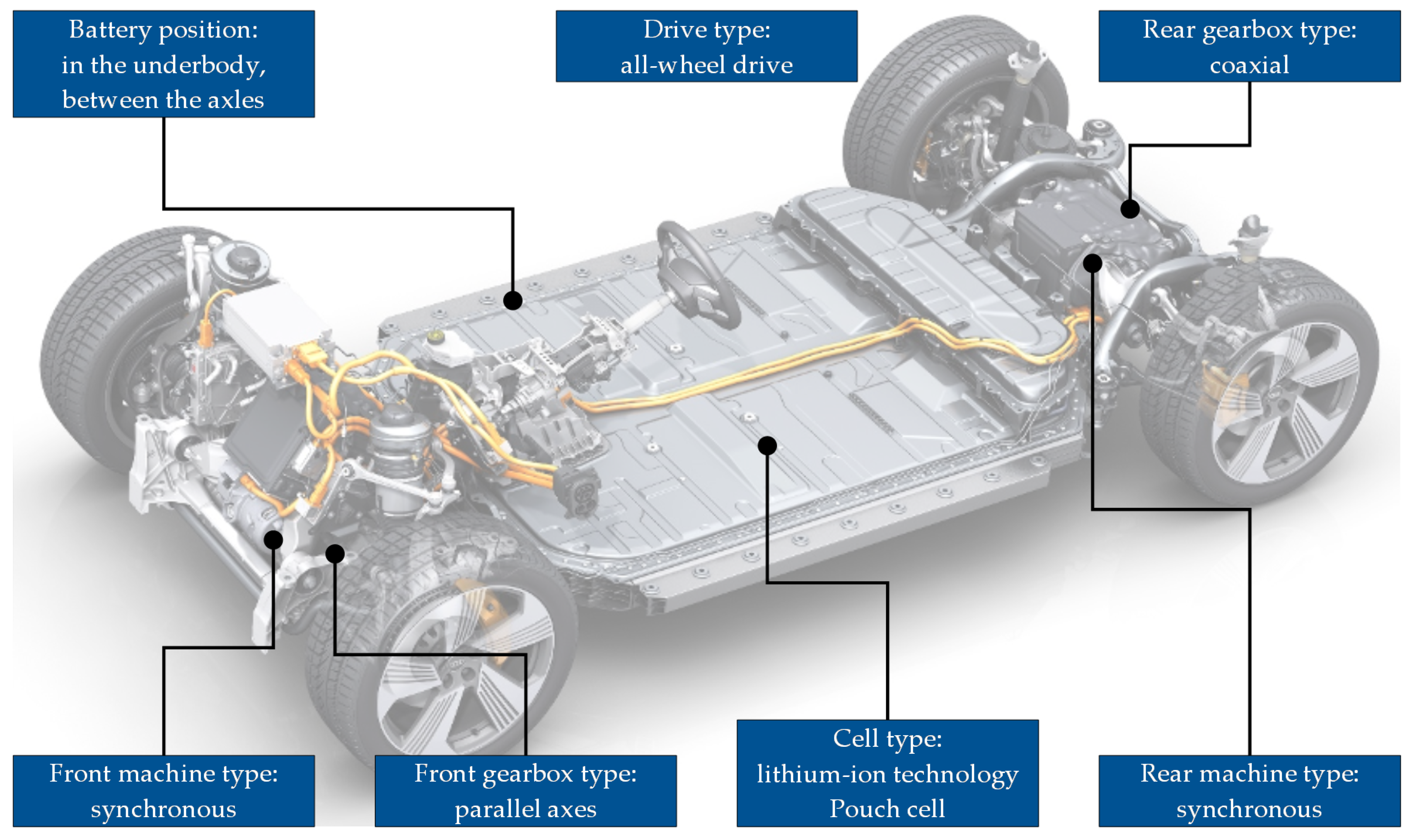
- Powertrain topology: The powertrain topology describes the rough layout and location of the BEV powertrain components. For example, the powertrain topology defines the location of the electric machine (front axle, rear axle) and its position regarding the axle (in front of the axle, behind the axle or coaxial). Further topology specifications are the type of gearbox (coaxial or with parallel axes) and the shape of the battery. An overview of the relevant topology components can be found in [11,12].
- Component models: The powertrain topology itself only defines the positioning of the powertrain components. Their volume and weight are derived using component models. In addition to the topology components, which describe the required space for the vehicle powertrain, further components have to be considered, such as wheels and axles. The latter define, with their dimensions, the available space for the powertrain components [4].
- Dimensional chains: The dimensional chains describe the geometrical interdependencies between the components in the X-, Y-, and Z-directions. Following the components’ dimensioning, the available installation space in the vehicle has to be compared with the required installation space using dimensional chains, thus enabling the testing of feasibility and collision. Further information is available in [5].
2.2. Complete Modeling of the Vehicle Architecture
- Modeling dimensional concept: We evaluate this category as fulfilled (●) if the author considers and models the main dimensions of the dimensional concept. Furthermore, the author needs to take into account the location of the passengers and their position. We consider this category as not entirely fulfilled (◑), if the author models only a part of the dimensional concept (for example only the first row of seats) and not fulfilled (○) if the dimensional concept is completely ignored.
- Modeling powertrain topology: We evaluate this category as fulfilled (●) if the author models all the possible BEV topologies, describing the position and rough location of the battery, electric machine, and gearbox. If only a limited number of components is modeled (for example, only the positioning of the battery), we consider this category as not entirely fulfilled (◑). An unfulfilled powertrain topology (○) means that the positioning and layout of the powertrain components are completely ignored.
- Modeling component models: We evaluate this category as fulfilled (●) if the author models the main vehicle components, including wheels, axles, and powertrain. Furthermore, an estimation of the required and available installation space must be possible. The category is not entirely fulfilled (◑) or not fulfilled (○), respectively, if the author models only a part or none of the relevant components.
- Modeling dimensional chains: We evaluate this category as fulfilled (●) if the author considers the relevant dimensional chains. The whole vehicle and not just specific areas (e.g., vehicle front, battery installation space, or interior) need to be considered. If only specific areas are modeled, the category is evaluated as not entirely fulfilled (◑). If the components are not positioned using dimensional chains, the category is not fulfilled (○).
2.3. Focus on Dimensional Concept and Dimensional Chains
2.4. Focus on Component Models and Powertrain Topology
3. Results
3.1. Relevant Parameters for the Dimensional Concept
3.2. Relevant Parameters for the Powertrain Topology
3.3. Relevant Parameters for the Component Models
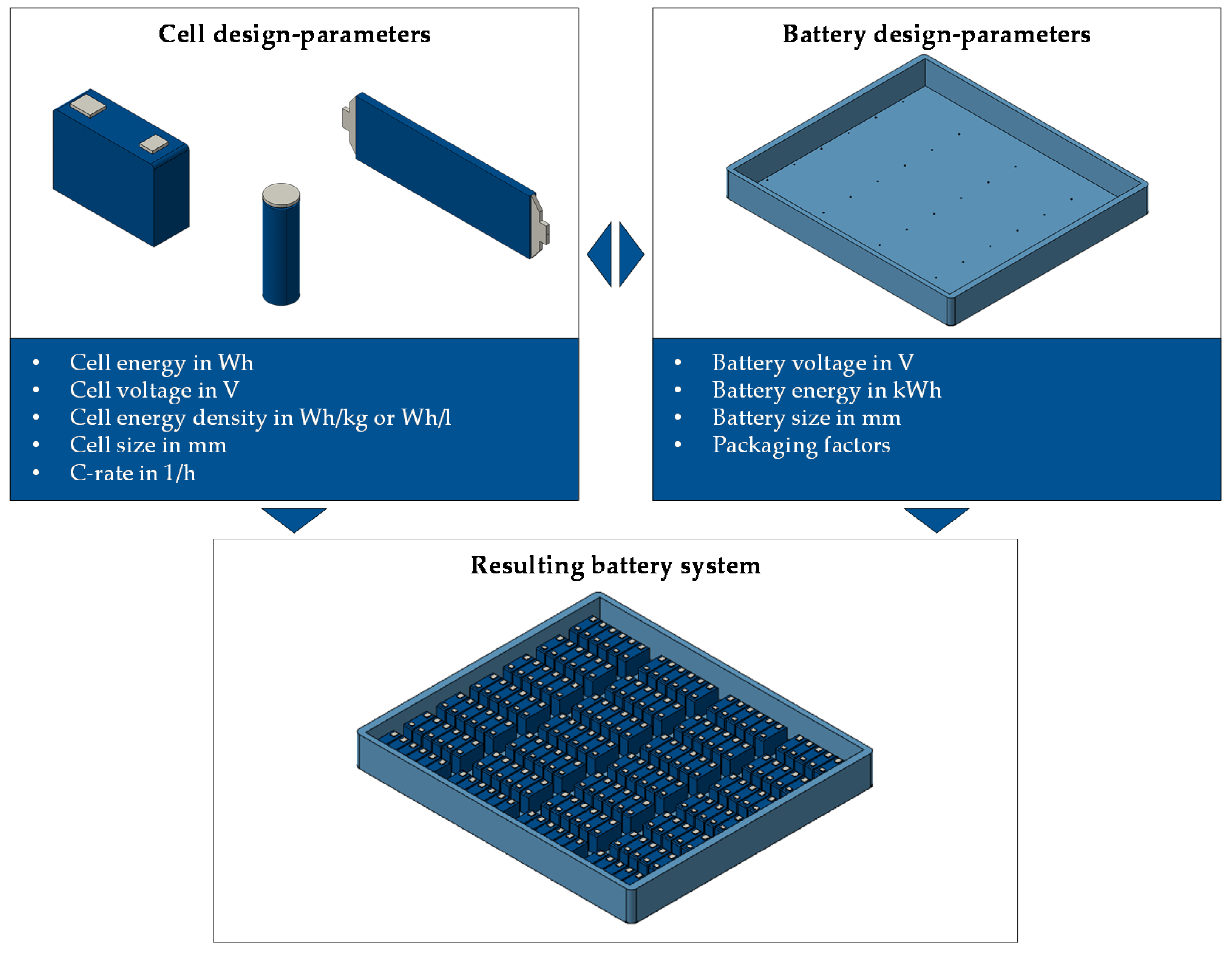
3.3.1. Traction Battery
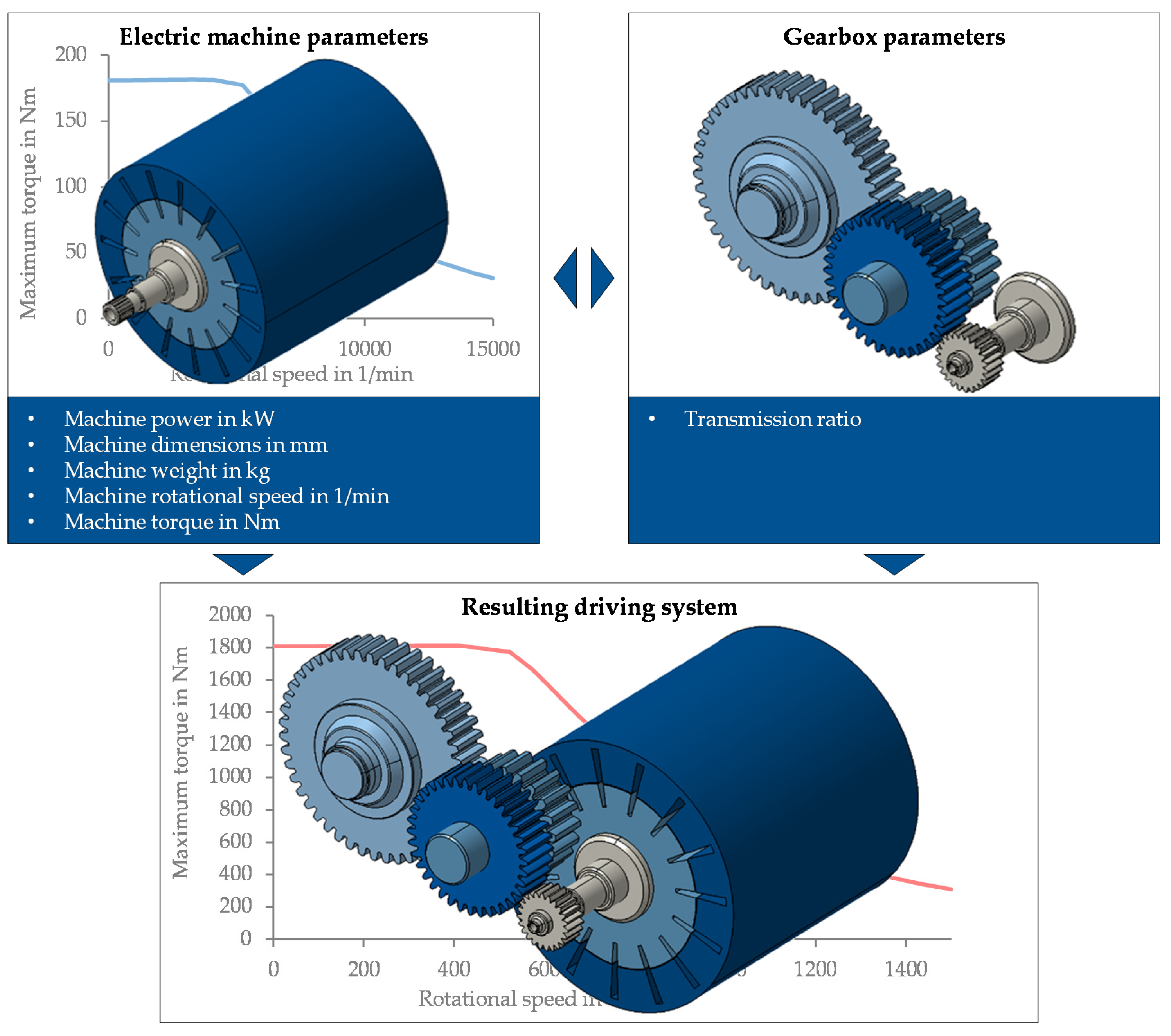
3.3.2. Electric Machine and Gearbox
3.3.3. Wheels and Axles
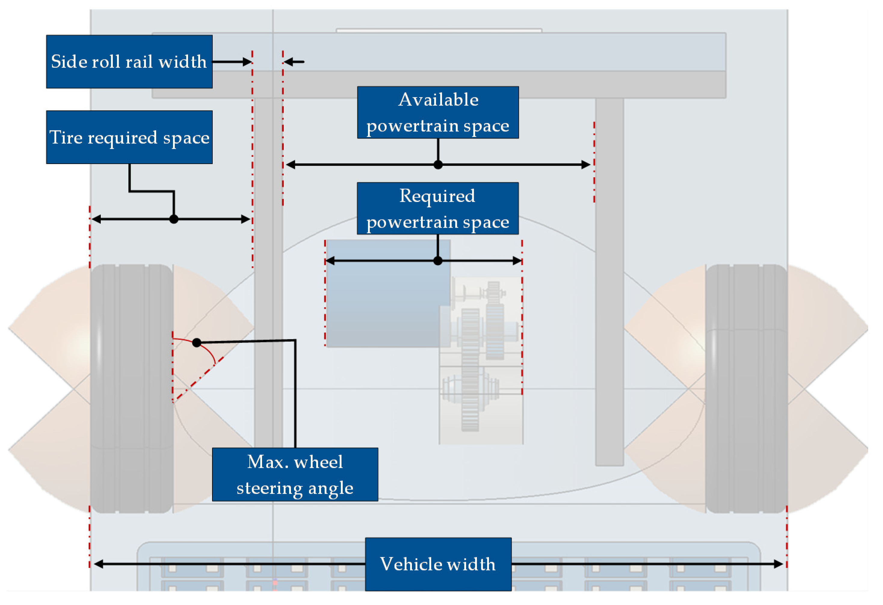
3.4. Relevant Parameters for the Dimensional Chains
3.5. Vehicle Characteristics and Properties
4. Discussion and Conclusions
Author Contributions
Funding
Acknowledgments
Conflicts of Interest
Appendix A

| Author | Modeling Dimensional Concept | Modeling Powertrain Topology | Modeling Component Models | Modeling Dimensional Chains |
|---|---|---|---|---|
| Angerer [13,14,15] | ○ | ● | ● | ◑ |
| Felgenhauer [16,17,18] | ◑ | ◑ | ● | ◑ |
| J. Fuchs [19,20] | ◑ | ● | ◑ | ◑ |
| Fabian, Stadler, Rossbacher [21,22,23] | ● | ● | ◑ | ● |
| Kuchenbuch [24,25,26] | ● | ● | ◑ | ◑ |
| Matz [27,28] | ◑ | ◑ | ◑ | ● |
| Raabe [1,29] | ● | ○ | ◑ | ● |
| Ried [30,31] | ◑ | ◑ | ◑ | ◑ |
| Sethuraman [32] | ◑ | ● | ◑ | ◑ |
| Stefaniak [33,34] | ◑ | ◑ | ○ | ◑ |
| Wiedemann [35,36] | ◑ | ◑ | ◑ | ◑ |
| Bhise [37,38] | ◑ | ○ | ○ | ◑ |
| Hahn [39] | ◑ | ○ | ○ | ◑ |
| Mau, Yanni [40,41,42] | ◑ | ○ | ○ | ◑ |
| Müller [43,85] | ● | ○ | ○ | ◑ |
| Prinz [44] | ◑ | ○ | ○ | ○ |
| Domingues [45,46,47] | ○ | ○ | ● | ○ |
| Eghtessad [48,49] | ○ | ◑ | ◑ | ○ |
| S. Fuchs [50,51] | ○ | ○ | ◑ | ○ |
| Hogt [52,53] | ○ | ◑ | ○ | ○ |
| Nemeth [54] | ○ | ◑ | ◑ | ○ |
| Pesce [55,56] | ○ | ● | ● | ○ |
References
- Raabe, R.; Maier, T.; Meyer-Eberling, J. Methodische gestaltung von abgesicherten maßkonzepten und parametrischen package-vorgabemodellen in der frühen phase der fahrzeugkonzeptauslegung. In Proceedings of the 4. Grazer Symposium Virtuelles Fahrzeug, Graz, Austria, 1 May 2011. [Google Scholar]
- Lindemann, U. Methodische Entwicklung Technischer Produkte; Springer: Berlin/Heidelberg, Germany, 2009; ISBN 978-3-642-01422-2. [Google Scholar]
- Kampker, A.; Vallée, D.; Schnettler, A. Elektromobilität; Springer: Berlin/Heidelberg, Germany, 2018; ISBN 978-3-662-53136-5. [Google Scholar]
- Nicoletti, L.; Schmid, W.; Lienkamp, M. Databased architecture modeling for electric vehicles: Submitted, accepted. In Proceedings of the Fifteenth International Conference on Ecological Vehicles and Renewable Energies, Nice, France, 12–14 October 2020. [Google Scholar]
- Nicoletti, L.; Mirti, S.; Schockenhoff, F.; König, A.; Lienkamp, M. Derivation of geometrical interdependencies between the passenger compartment and the traction battery using dimensional chains. World Electr. Veh. J. 2020, 11, 39. [Google Scholar] [CrossRef]
- SAE J826-Devices for Use in Defining and Measuring Vehicle Seating Accommodation, J826. 2015. Available online: https://www.sae.org/standards/content/j826_201511/ (accessed on 28 May 2020).
- SAE J1100—Motor Vehicle Dimensions, J1100. 2009. Available online: https://www.sae.org/standards/content/j1100_200911/ (accessed on 28 May 2020).
- SAE J4002—H-Point Machine (Hpm-Ii) Specifications and Procedure for H-Point Determination-Auditing Vehicle Seats, J4002. 2004. Available online: https://www.sae.org/standards/content/j4002_201001/ (accessed on 28 May 2020).
- SAE J1052—Motor Vehicle Driver and Passenger Head Position, J1052. 2017. Available online: https://www.sae.org/standards/content/j1052_201710/ (accessed on 22 May 2020).
- SAE J941—Motor Vehicle Drivers’ Eye Locations, J941. 2010. Available online: https://www.sae.org/standards/content/j941_201003/ (accessed on 22 May 2020).
- Nicoletti, L.; Ostermann, F.; Heinrich, M.; Stauber, A.; Lin, X.; Lienkamp, M. Topology analysis of electric vehicles, with a focus on the traction battery. Forsch. Ing. 2020. submitted. [Google Scholar]
- Kasper, R.; Schünemann, M. 5. Elektrische Fahrantriebe Topologien Und Wirkungsgrad. MTZ-Mot. Z. 2012, 73, 802–807. [Google Scholar] [CrossRef]
- Angerer, C. Antriebskonzept-Optimierung für Batterieelektrische Allradfahrzeuge. Ph.D. Thesis, Institute of Automotive Technology, Technical University of Munich, Munich, Germany, 2020. [Google Scholar]
- Angerer, C.; Felgenhauer, M.; Eroglu, I.; Zahringer, M.; Kalt, S.; Lienkamp, M. Scalable dimension-, weight- and cost-modeling for components of electric vehicle powertrains. In Proceedings of the 2018 21th International Conference on Electrical Machines and Systems (ICEMS), Jeju, Korea, 7–10 October 2018; pp. 966–973. [Google Scholar]
- Angerer, C.; Krapf, S.; Buß, A.; Lienkamp, M. Holistic modeling and optimization of electric vehicle powertrains considering longitudinal performance, vehicle dynamics, costs and energy consumption. In Proceedings of the ASME International Design Engineering Technical Conferences and Computers and Information in Engineering Conference 2018, Quebec City, QC, Canada, 26–29 August 2018. [Google Scholar]
- Felgenhauer, M.; Angerer, C.; Marksteiner, R.; Schneider, F.; Lienkamp, M.L. Geometric substitute models for efficient scaling of dimensions during vehicle architecture design. In Proceedings of the DESIGN 2018 15th International Design Conference, Dubrovnik, Croatia, 21–24 May 2018; pp. 261–272. [Google Scholar]
- Felgenhauer, M.; Nicoletti, L.; Schockenhoff, F.; Angerer, C.; Lienkamp, M. Empiric weight model for the early phase of vehicle architecture design. In Proceedings of the Fourteenth International Conference on Ecological Vehicles and Renewable Energies (EVER), Monte-Carlo, Monaco, 8–10 May 2019. [Google Scholar]
- Felgenhauer, M. Automated Development of Modular Systems for the Vehicle Front of Passenger Cars. Ph.D. Thesis, Institute of Automotive Technology, Technical University of Munich, Munich, Germany. Available online: https://mediatum.ub.tum.de/1473406 (accessed on 7 June 2020).
- Fuchs, J. Analyse der Wechselwirkungen und Entwicklungspotentiale in der Auslegung Elektrifizierter Fahrzeugkonzepte, 1st ed.; Cuvillier Verlag: Munich, Germany, 2014; ISBN 9783954048748. [Google Scholar]
- Fuchs, J.; Lienkamp, M. Technologies and architectures for electrified vehicles. ATZ Worldw. 2013, 115, 4–10. [Google Scholar] [CrossRef]
- Fabian, J.; Hirz, M.; Krischan, K. State of the art and future trends of electric drives and power electronics for automotive engineering. SAE Int. J. Passeng. Cars Electron. Electr. Syst. 2014, 7, 293–303. [Google Scholar] [CrossRef]
- Stadler, S.; Hirz, M.; Thum, K.; Rossbacher, P. Conceptual full-vehicle development supported by integrated computer-aided design methods. Comput. Des. Appl. 2013, 10, 159–172. [Google Scholar] [CrossRef] [Green Version]
- Rossbacher, P.; Hirz, M. Flexible parameterization strategies in automotive 3D vehicle layout. Comput. Des. Appl. 2017, 14, 549–562. [Google Scholar] [CrossRef]
- Kuchenbuch, K. Methodik zur Identifikation und zum Entwurf Packageoptimierter Elektrofahrzeuge. Ph.D. Thesis, Technische Universität Carolo-WIlhelmina zu Braunschweig, Braunschweig, Germany, 2012. [Google Scholar]
- Kuchenbuch, K.; Stieg, J.; Vietor, T. Individual Concepts for Electric Vehicles: Interaction between Battery Package and Vehicle Concept. Volkswagen Konzernforschung—Volkswagen Group Research Wolfsburg. 2012. Available online: https://www.researchgate.net/publication/281968885_Individual_concepts_for_electric_vehicles_Interaction_between_battery_package_and_vehicle_concept (accessed on 7 June 2020).
- Kuchenbuch, K.; Vietor, T.; Stieg, J. Optimierungsalgorithmen für den Entwurf von Elektrofahrzeugen. ATZ Automob. Z. 2011, 113, 548–551. [Google Scholar] [CrossRef]
- Matz, S. Nutzorientierte Fahrzeugkonzeptoptimierung in Einer Multimodalen Verkehrsumgebung. Ph.D. Thesis, Institute of Automotive Technology, Technical University of Munich, Munich, Germany, 2015. [Google Scholar]
- Matz, S. Description of the Modelling Style and Parameters for Electric Vehicles in the Concept Phase. Available online: https://www.researchgate.net/publication/301517196_Description_of_the_modelling_style_and_parameters_for_electric_vehicles_in_the_concept_phase (accessed on 22 May 2020).
- Raabe, R. Ein Rechnergestützes Werkzeug zur Generierung Konsistenter Pkw-Maßkonzepte und Parametrischer Designvorgabe. Ph.D. Thesis, Inst. für Konstruktionstechnik und Technisches Design, Universität Stuttgart, Stuttgart, Germany, 2013. [Google Scholar]
- Ried, M.; Kelnberger, A.; Gumm, A.; Jung, M.; Schramm, D. Parametrische geometriemodelle für die konzeptgestaltung elektrifizierter fahrzeuge. Schritte künftige Mobilität 2013, 19–33. [Google Scholar] [CrossRef]
- Ried, M. Lösungsraumanalyse für Plug-In-Hybridfahrzeuge Hinsichtlich Wirtschaftlichkeit und Bauraumkonzept. Ph.D. Thesis, Universität Duisburg-Essen, Duisburg-Essen, Germany, 2016. [Google Scholar]
- Sethuraman, G.; Schwarz, M.; Maxl, S.; Ongel, A.; Lienkamp, M.; Hoeng, W.N. Development of an overall vehicle sizing and packaging tool for autonomous electric buses in the early concept phase. Int. J. Automot. Technol. 2020. [Google Scholar] [CrossRef]
- Stefaniak, T.; Maiwald, D. Ermittlung Nutzbarer Bauräume für Energiespeicher auf Hochvoltebene in Elektrofahrzeugen mit Dezentralisierten Antriebssträngen. In 13. Magdeburger Maschinenbau-Tage, Magdeburg. 2017. Available online: https://www.researchgate.net/publication/320196213_Ermittlung_nutzbarer_Bauraume_fur_Energiespeicher_auf_Hochvoltebene_in_Elektrofahrzeugen_mit_dezentralisierten_Antriebsstrangen (accessed on 18 November 2019).
- Stefaniak, T.; Maiwald, D.; Püschel, G.; Durch Maßkonzept und Algorithmen zur optimierten Fahrzeugbatterie: By Means of Measurement Concept and Algorithms to the Optimized Vehicle Battery. Konstruktion: Zeitschrift für Produktentwicklung und Ingenieur-Werkstoffe, no. 4. 2018. Available online: https://www.researchgate.net/publication/324504486_Durch_Masskonzept_und_Algorithmen_zur_optimierten_Fahrzeugbatterie/references (accessed on 7 June 2020).
- Wiedemann, E. Ableitung von Elektrofahrzeugkonzepten aus Eigenschaftszielen, 1st ed.; Cuvillier Verlag: Munich, Germany, 2014; ISBN 9783954047895. [Google Scholar]
- Wiedemann, E.; Meurle, J.; Lienkamp, M. Optimization of electric vehicle concepts based on customer-relevant characteristics. SAE Tech. Pap. Ser. 2012. [Google Scholar] [CrossRef]
- Bhise, V.; Kridli, G.; Mamoola, H.; Devaraj, S.; Pillai, A.; Shulze, R. Development of a parametric model for advanced vehicle design. SAE Tech. Pap. Ser. 2004. [Google Scholar] [CrossRef]
- Bhise, V.; Pillai, A. A Parametric Model for Automotive Packaging and Ergonomics Design. Available online: http://citeseerx.ist.psu.edu/viewdoc/download?doi=10.1.1.90.4564&rep=rep1&type=pdf (accessed on 20 November 2019).
- Hahn, J. Eigenschaftsbasierte Fahrzeugkonzeption: Eine Methodik in der Frühen Konzeptphase; Springer: Magdeburg, Germany, 2017; ISBN 9783658201005. [Google Scholar]
- Mau, R.J.; Venhovens, P.J. Parametric vehicle mass estimation for optimization. Int. J. Veh. Des. 2016, 72, 1. [Google Scholar] [CrossRef]
- Yanni, T.; Venhovens, P.J.T. Impact and sensitivity of vehicle design parameters on fuel economy estimates. SAE Tech. Pap. Ser. 2010. [Google Scholar] [CrossRef]
- Mau, R.J.; Venhovens, P.J. Development of a consistent continuum of the dimensional parameters of a vehicle for optimization and simulation. Proc. Inst. Mech. Eng. Part D J. Automob. Eng. 2014, 228, 591–603. [Google Scholar] [CrossRef]
- Müller, A. Systematische und Nutzerzentrierte Generierung des Pkw-Maßkonzepts als Grundlage des Interior- und Exteriordesign; IKTD: Stuttgart, Germany, 2010; ISBN 9783922823773. [Google Scholar]
- Prinz, A. Struktur und Ablaufmodell für das Parametrische Entwerfen von Fahrzeugkonzepten; AutoUni-Schriftenreihe: Braunschweig, Germany, 2011; ISBN 9783832528690. [Google Scholar]
- Domingues, G.; Marquez-Fernandez, F.J.; Fyhr, P.; Reinap, A.; Andersson, M.; Alakula, M. Scalable performance, efficiency and thermal models for electric drive components used in powertrain simulation and optimization. In Proceedings of the 2017 IEEE Transportation and Electrification Conference and Expo (ITEC), Chicago, IL, USA, 22–24 June 2017; pp. 644–649. [Google Scholar]
- Domingues, G.; Reinap, A.; Alakula, M. Design and cost optimization of electrified automotive powertrain. In Proceedings of the ESARS-ITEC International Conference on Electrical Systems for Aircraft, Railway, Ship Propulsion and Road Vehicles & International Transportation Electrification Conference, Toulouse, France, 2–4 November 2016; pp. 1–6. [Google Scholar]
- Domingues-Olavarria, G.; Fyhr, P.; Reinap, A.; Andersson, M.; Alakula, M. From chip to converter: A complete cost model for power electronics converters. IEEE Trans. Power Electron. 2017, 32, 8681–8692. [Google Scholar] [CrossRef]
- Eghtessad, M.; Meier, T.; Rinderknecht, S.; Küçükay, F. Antriebsstrangoptimierung von Elektrofahrzeugen. ATZ Automob. Z. 2015, 117, 78–85. [Google Scholar] [CrossRef]
- Eghtessad, M.; Meier, T.; Rinderknecht, S.; Küçükay, F. Powertrain optimisation of electric vehicles. ATZ Worldw. 2015, 117, 48–53. [Google Scholar] [CrossRef]
- Fuchs, S.; Lienkamp, M. Parametric Modelling of Mass and Efficiency of New Vehicle Concepts. ATZ Worldw. 2013, 115, 60–67. [Google Scholar] [CrossRef]
- Fuchs, S. Verfahren zur Parameterbasierten Gewichtsabschätzung Neuer Fahrzeugkonzepte: Ein Werkzeug zur Spezifikation von Effizienten Antriebstopologien für Elektrofahrzeuge. Ph.D. Thesis, Institute of Automotive Technology, Technical University of Munich, Munich, Germany. Available online: mediatum.ub.tum.de/1207264 (accessed on 12 June 2019).
- Hogt, R. Electric Vehicle Packaging Tool (EVPT). EEVC: Brussels, Belgium, 2012. Available online: https://www.fabulo.nl/paper%20eevc2012__470037_roelandhogt_evpt_v001.pdf (accessed on 12 February 2020).
- Hogt, R.; Rieck, F.G. Electric Vehicle Packaging Tool (EVPT), validation and application. In Proceedings of the World Electric Vehicle Symposium and Exposition (EVS 27), Barcelona, Spain, 17–20 November 2013; pp. 1–12. [Google Scholar]
- Nemeth, T.; Bubert, A.; Becker, J.N.; de Doncker, R.W.; Sauer, D.U. A Simulation Platform for Optimization of Electric Vehicles with Modular Drivetrain Topologies. IEEE Trans. Transp. Electrif. 2018, 4, 888–900. [Google Scholar] [CrossRef]
- Pesce, T. Ein Werkzeug zur Spezifikation von Effizienten Antriebstopologien für Elektrofahrzeuge; Verlag: Munich, Germany, 2014; ISBN 3843916241. [Google Scholar]
- Pesce, T.; Lienkamp, M. Definition and optimization of the drive train topology for electric vehicles. World Electr. Veh. J. 2012, 5, 24–35. [Google Scholar] [CrossRef] [Green Version]
- Mayer, S. Literaturrecherche: Packagemodellierung. Semester Thesis, Chair of Automotive Technology, Technical University of Munich, Munich, Germany, 2020. [Google Scholar]
- Walz, M.C. Trends in the Static Stability Factor of Passenger Cars, Light Trucks, Vans. U.S. Departement of Transportation, National Highway Traffic Safety Administration: Washington, DC, USA, 2005. Available online: https://crashstats.nhtsa.dot.gov/Api/Public/ViewPublication/809868 (accessed on 23 May 2020).
- Regulation No 125 of the Economic Commission for Europe of the United Nations (UN/ECE)—Uniform Provisions Concerning the Approval of Motor Vehicles with Regard to the Forward Field of Vision of the Motor Vehicle Driver: ECE R125. 2010. Available online: http://data.europa.eu/eli/reg/2010/125(2)/oj (accessed on 12 December 2019).
- Federal Government of the United States, Code of Federal Regulations, Section § 523.5—Light truck, 49 CFR 523.5. 1998. Available online: https://www.govinfo.gov/app/details/CFR-1998-title49-vol5/CFR-1998-title49-vol5-sec523-5 (accessed on 11 November 2019).
- Federal Government of the United States, Code of Federal Regulations, Section § 523.2—Definitions, 49 CFR 523.2. 2018. Available online: https://www.govinfo.gov/app/details/CFR-2018-title49-vol6/CFR-2018-title49-vol6-sec523-2/summary (accessed on 11 November 2019).
- KMVSS—Regulations for Performance and Safety Standards of Motor Vehicle and Vehicle Parts, Molit Ord. 252. Available online: http://ec.europa.eu/growth/tools-databases/tbt/en/search/?tbtaction=get.project&Country_ID=KOR&num=710&dspLang=EN&basdatedeb=,&basdatefin=&baspays=KOR&baspays2=KOR&basnotifnum=710&basnotifnum2=710&bastypepays=KOR&baskeywords=&project_type_num=1&project_type_id=12&lang_id=EN (accessed on 11 November 2019).
- Directive 2007/46/Ec of the European Parliament and of the Council of 5 September 2007 Establishing a Framework for the Approval of Motor Vehicles and Their Trailers, of Systems, Components and Separate Technical Units Intended for Such Vehicles: 2007/46/EC. 2007. Available online: http://data.europa.eu/eli/dir/2007/46/oj (accessed on 12 December 2019).
- Vehicle Configuration and Dimensions, Australian Design Rule 43/04. 2006. Available online: https://www.legislation.gov.au/Details/F2006L01430 (accessed on 1 October 2019).
- Guzzella, L.; Sciarretta, A. Vehicle Propulsion Systems; Springer: Berlin/Heidelberg, Germany, 2013; ISBN 978-3-642-35912-5. [Google Scholar]
- Haken, K.-L. Grundlagen der Kraftfahrzeugtechnik: Mit 36 Tabellen, 2nd ed.; München: Hanser, Germany, 2011; ISBN 9783446428492. [Google Scholar]
- Audi, A.G. A4 Avant > A4 > Audi Deutschland. Available online: https://www.audi.de/de/brand/de/neuwagen/a4/a4-avant.html (accessed on 23 May 2020).
- Karle, A. Elektromobilität: Grundlagen und Praxis, 3rd ed.; Fachbuchverlag Leipzig im Carl Hanser Verlag: Munich, Germany, 2018; ISBN 9783446456686. [Google Scholar]
- Rimac Automobili, Concept_One. Rimac Automobili. Available online: https://www.rimac-automobili.com/en/hypercars/concept_one/ (accessed on 26 May 2020).
- Doerr, J.; Ardey, N.; Mendl, G.; Fröhlich, G.; Straßer, R.; Laudenbach, T. The new full electric drivetrain of the Audi e-tron. Antr. Morgen 2019, 13–37. [Google Scholar] [CrossRef]
- Thielmann, A.; Sauer, A.; Wietschel, M. Gesamt-Roadmap Energiespeicher für die Elektromobilität 2030. Available online: https://www.isi.fraunhofer.de/content/dam/isi/dokumente/cct/lib/GRM-ESEM.pdf (accessed on 27 May 2020).
- Thielmann, A.; Neef, C.; Hettesheimer, T.; Döscher, H.; Wietschel, M.; Tubke, J. Energiespeicher-Roadmap (Update 2017): Hochenergie-Batterien 2030+ und Perspektiven zukünftiger Batterietechnologien. 2017. Available online: http://publica.fraunhofer.de/eprints/urn_nbn_de_0011-n-4812318.pdf (accessed on 27 May 2020).
- Fink, H. Li-ion batteries for automotive applications—Quo vadis? Int. Stuttg. Symp. 2016, 69–81. [Google Scholar] [CrossRef]
- Busche, I. Ein Beitrag zur Optimierten Konzeptauslegung von Fahrzeugen im Bereich der Elektromobilität. Ph.D. Thesis, Fakultät für Maschinenbau, Universität Magdeburg, Magdeburg, Germany, 2014. [Google Scholar]
- Insurance Institute for Highway Safety, Side Impact Crashworthiness Evaluation—Crash Test Protocol (Version X). 2017. Available online: https://www.iihs.org/ratings/about-our-tests/test-protocols-and-technical-information (accessed on 13 May 2020).
- Insurance Institute for Highway Safety, Small Overlap Frontal Crashworthiness Evaluation—Crash Test Protocol (Version VI). 2017. Available online: https://www.iihs.org/ratings/about-our-tests/test-protocols-and-technical-information (accessed on 27 May 2020).
- Justen, R.; Schöneburg, R. Crash Safety of Hybrid- and Battery Electric Vehicles. 22nd International Technical Conference on the Enhanced Safety of Vehicles (ESV). 2011. Available online: https://www-esv.nhtsa.dot.gov/Proceedings/22/files/22ESV-000096.pdf (accessed on 21 May 2020).
- Grunditz, E.A.; Thiringer, T. Performance Analysis of Current BEVs Based on a Comprehensive Review of Specifications. IEEE Trans. Transp. Electrif. 2016, 2, 270–289. [Google Scholar] [CrossRef]
- Marksteiner, R. Ableitung von Korrelationen für den Bauraumbedarf von Antriebskomponenten. Master’s Thesis, Institute of Automotive Technology, Technical University of Munich, Munich, Germany, 2017. [Google Scholar]
- Luccarelli, M.; Lienkamp, M.; Matt, D.; Spena, P.R. Automotive design quantification: Parameters defining exterior proportions according to car segment. SAE Tech. Pap. Ser. 2014. [Google Scholar] [CrossRef]
- European Tyre and Rim Technical Organisation. Standards Manual 2020. Available online: https://www.etrto.org/Publications/Order/STANDARDS-MANUAL-2018 (accessed on 29 June 2020).
- Weber, C. Looking at “DFX” and “product maturity” from the perspective of a new approach to modelling product and product development processes. Future Prod. Dev. 2007, 85–104. [Google Scholar] [CrossRef]
- Ziemann, A. Zielsystemmanagement für die Produktentstehung von PKW. Ph.D. Thesis, Institute of Automotive Technology, Technical University of Munich, Munich, Germany, 2007. [Google Scholar]
- Weber, J. Automotive Development Processes; Springer: Berlin/Heidelberg, Germany, 2009; ISBN 978-3-642-01252-5. [Google Scholar]
- Müller, A.; Maier, T. Vehicle layout conception considering trunk loading and unloading. Adv. Appl. Digit. Hum. Model. 2011, 84–93. [Google Scholar] [CrossRef]


| Author | Modeling Dimensional Concept | Modeling Powertrain Topology | Modeling Component Models | Modeling Dimensional Chains |
|---|---|---|---|---|
| Angerer [13,14,15] | ○ | ● | ● | ◑ |
| Felgenhauer [16,17,18] | ◑ | ◑ | ◑ | ◑ |
| J. Fuchs [19,20] | ◑ | ● | ◑ | ◑ |
| Fabian, Stadler, Rossbacher [21,22,23] | ● | ● | ◑ | ● |
| Kuchenbuch [24,25,26] | ● | ● | ◑ | ◑ |
| Matz [27,28] | ◑ | ◑ | ◑ | ● |
| Raabe [1,29] | ● | ○ | ◑ | ● |
| Ried [30,31] | ◑ | ◑ | ◑ | ◑ |
| Sethuraman [32] | ◑ | ● | ◑ | ◑ |
| Stefaniak [33,34] | ◑ | ◑ | ○ | ◑ |
| Wiedemann [35,36] | ◑ | ◑ | ◑ | ◑ |
| Parameter | Sources |
|---|---|
| Vehicle length, overhangs, and wheelbase in mm | Angerer [13,14,15], Bhise [37,38], Felgenhauer [16,17,18], J. Fuchs [19,20], S. Fuchs [50,51], Hahn [39], Hogt [52,53], Matz [27,28], Pesce [55,56], Prinz [44], Raabe [1,29], Sethuraman [32], Stefaniak [33,34], Wiedemann [35,36] |
| Vehicle width and track width in mm | Angerer [13,14,15], Bhise [37,38], Felgenhauer [16,17,18], J. Fuchs [19,20], S. Fuchs [50,51], Hahn [39], Matz [27,28], Raabe [1,29], Ried [30,31], Sethuraman [32], Prinz [44], Stefaniak [33,34] |
| Seating reference point (SgRP) position in mm | Bhise [37,38], Felgenhauer [16,17,18], J. Fuchs [19,20], Hahn [39], Matz [27,28], Prinz [44], Raabe [1,29], Ried [30,31], Stefaniak [33,34] |
| Vehicle height in mm | Angerer [13,14,15], Bhise [37,38], J. Fuchs [19,20], S. Fuchs [50,51], Hahn [39], Matz [27,28], Raabe [1,29], Sethuraman [32], Wiedemann [35,36] |
| Ground clearance in mm | J. Fuchs [19,20], Hahn [39], Kuchenbuch [24,25,26], Raabe [1,29], Ried [30,31], Sethuraman [32], Stefaniak [33,34] |
| Number of seats | S. Fuchs [50,51], Hahn [39], Matz [27,28], Prinz [44], Sethuraman [32], Wiedemann [35,36] |
| Headroom in mm | Bhise [37,38], Hahn [39], Kuchenbuch [24,25,26], Prinz [44], Raabe [1,29], Wiedemann [35,36] |
| Legroom in mm | Hahn [39], Prinz [44], Raabe [1,29], Sethuraman [32], Wiedemann [35] |
| Front area in m2 | J. Fuchs [19,20], Hahn [39], Nemeth [29], Pesce [55,56], Prinz [44] |
| Acceleration heel point (AHP) position in mm | Bhise [37,38], Hahn [39], Raabe [1,29], Stefaniak [33,34] |
| Length of crash in mm | Kuchenbuch [24,25,26], Prinz [44], Raabe [1,29] |
| Parameter | Sources |
|---|---|
| Cell type | Eghtessad [48], Felgenhauer [16,17,18], J. Fuchs [19,20], S. Fuchs [50,51], Kuchenbuch [24,25,26], Matz [27,28], Nemeth [54], Pesce [55,56], Wiedemann [35,36] |
| Electric machine type | Angerer [13,14,15], Domingues [45,46,47], Eghtessad [48], Felgenhauer [16,17,18], J. Fuchs [19,20], S. Fuchs [50,51], Matz [27,28], Nemeth [54], Pesce [55,56], Wiedemann [35,36] |
| Drive type | Angerer [13,14,15], Eghtessad [48], Felgenhauer [16,17,18], J. Fuchs [19,20], S. Fuchs [50,51], Hahn [39], Matz [27,28], Wiedemann [35,36] |
| Gearbox type | Angerer [13,14,15], Domingues [45,46,47], Eghtessad [48], Felgenhauer [16,17,18], J. Fuchs [19,20], S. Fuchs [50,51], Wiedemann [35,36] |
| Battery position and shape | Kuchenbuch [24,25,26], Hogt [52,53], Matz [27,28], Prinz [44], Wiedemann [35,36] |
| Parameter | Sources |
|---|---|
| Cell energy in Wh | J. Fuchs [19,20], Kuchenbuch [24,25,26], Matz [27,28], Nemeth [54], Stefaniak [33,34], Wiedemann [35,36] |
| Cell voltage in V | J. Fuchs [19,20], Kuchenbuch [24,25,26], Matz [27,28], Nemeth [54], Stefaniak [33,34] |
| Cell energy density in Wh/kg or Wh/L | Angerer [13,14,15], J. Fuchs [19,20], S. Fuchs [50,51], Nemeth [54], Wiedemann [35,36] |
| Cell size in mm | Kuchenbuch [24,25,26], Matz [27,28], Sethuraman [32], Stefaniak [33,34] |
| C-rate in 1/h | J. Fuchs [19,20], Matz [27,28], Wiedemann [35,36] |
| Parameter | Sources |
|---|---|
| Battery voltage in V | Domingues [45,46,47], J. Fuchs [19,20], Matz [27,28], Pesce [55,56], Stefaniak [33,34], Wiedemann [35,36] |
| Battery energy in kWh | Eghtessad [48], Felgenhauer [16,17,18], Matz [27,28], Pesce [55,56] |
| Battery size in mm | Felgenhauer [16,17,18], Kuchenbuch [24,25,26], Prinz [44], Sethuraman [32] |
| Packinging factors | J. Fuchs [19,20], S. Fuchs [50,51], Matz [27,28], Wiedemann [35,36] |
| Parameter | Sources |
|---|---|
| Machine rotational speed in 1/min | Angerer [13,14,15], Eghtessad [48], J. Fuchs [19,20], S. Fuchs [50,51], Kuchenbuch [24,25,26], Pesce [55,56], Wiedemann [35,36] |
| Machine torque in Nm | Angerer [13,14,15], Domingues [45,46,47], Eghtessad [48], J. Fuchs [19,20], S. Fuchs [50,51], Pesce [55,56], Wiedemann [35,36] |
| Machine power in kW | Domingues [45,46,47], J. Fuchs [19], Hahn [39], Hogt [52,53], Kuchenbuch [24,25,26], Wiedemann [35,36] |
| Machine dimensions in mm | Kuchenbuch [24,25,26], Sethuraman [32], Wiedemann [35,36] |
| Machine weight in kg | J. Fuchs [19,20], Matz [27,28], Prinz [44], Wiedemann [35,36] |
| Gearbox transmission ratio | Angerer [13,14,15], Eghtessad [48], J. Fuchs [19,20], S. Fuchs [50,51], Matz [27,28], Pesce [55,56], Wiedemann [35,36] |
| Parameter | Sources |
|---|---|
| Tire diameter in mm | Angerer [13,14,15], Bhise [37,38], Felgenhauer [16,17,18], J. Fuchs [19,20], S. Fuchs [50,51], Kuchenbuch [24,25,26], Matz [27,28], Nemeth [54], Pesce [55,56], Prinz [44], Raabe [1,29], Ried [30,31], Sethuraman [32], Wiedemann [35] |
| Rolling resistance factor | Angerer [13,14,15], S. Fuchs [50,51], Kuchenbuch [24,25,26], Matz [27,28], Nemeth [54] |
| Width in mm | Angerer [13,14,15], Bhise [37,38], S. Fuchs [50,51], Kuchenbuch [24,25,26], Matz [27,28] |
| Tire type | Felgenhauer [16,17,18], S. Fuchs [50,51], Matz [27,28] |
| Axles type | Felgenhauer [16,17,18], S. Fuchs [50,51], Matz [27,28] |
| Parameter | Sources |
|---|---|
| Acceleration time in s | Felgenhauer [16,17,18], J. Fuchs [19,20], S. Fuchs [50,51], Hahn [39], Nemeth [54], Pesce [55,56], Prinz [44], Wiedemann [35,36] |
| Maximum velocity in m/s | Domingues [45,46,47], Felgenhauer [16,17,18], J. Fuchs [19,20], Hahn [39], Hogt [52,53], Pesce [55,56], Prinz [44], Wiedemann [35,36] |
| Vehicle segment | Bhise [37,38], Domingues [45,46,47], Felgenhauer [16,17,18], J. Fuchs [19,20], S. Fuchs [50,51], Prinz [44], Wiedemann [35,36] |
| Range in km | J. Fuchs [19,20], S. Fuchs [50,51], Hogt [52,53], Nemeth [54], Pesce [55,56], Wiedemann [35,36] |
| Turning circle in m | Felgenhauer [16,17,18], Hahn [39], Prinz [44], Wiedemann [35,36] |
| Parameter | Sources |
|---|---|
| Vehicle weight in kg | Domingues [45,46,47], Felgenhauer [16,17,18], J. Fuchs [19,20], S. Fuchs [50,51], Hahn [39], Hogt [52,53], Nemeth [54], Pesce [55,56], Prinz [44], Wiedemann [35,36] |
| Drag coefficient | J. Fuchs [19,20], Hahn [39], Kuchenbuch [24,25,26], Nemeth [54], Pesce [55,56], Prinz [44], Wiedemann [35,36] |
| Axle load ratios in% | J. Fuchs [19,20], Matz [27,28], Pesce [55,56], Wiedemann [35,36] |
| Position center of gravity (COG) in mm | Hogt [52,53], Pesce [55,56], Prinz [44] |
| Group | Number of Parameters |
|---|---|
| Dimensional Concept (Table 2) | 14 |
| Powertrain topology (Table 3) | 6 |
| Component models (Table 4, Table 5, Table 6 and Table 7) | 20 |
| Vehicle properties (Table 8) and vehicle characteristics (Table 9) | 9 |
© 2020 by the authors. Licensee MDPI, Basel, Switzerland. This article is an open access article distributed under the terms and conditions of the Creative Commons Attribution (CC BY) license (http://creativecommons.org/licenses/by/4.0/).
Share and Cite
Nicoletti, L.; Mayer, S.; Brönner, M.; Schockenhoff, F.; Lienkamp, M. Design Parameters for the Early Development Phase of Battery Electric Vehicles. World Electr. Veh. J. 2020, 11, 47. https://0-doi-org.brum.beds.ac.uk/10.3390/wevj11030047
Nicoletti L, Mayer S, Brönner M, Schockenhoff F, Lienkamp M. Design Parameters for the Early Development Phase of Battery Electric Vehicles. World Electric Vehicle Journal. 2020; 11(3):47. https://0-doi-org.brum.beds.ac.uk/10.3390/wevj11030047
Chicago/Turabian StyleNicoletti, Lorenzo, Sebastian Mayer, Matthias Brönner, Ferdinand Schockenhoff, and Markus Lienkamp. 2020. "Design Parameters for the Early Development Phase of Battery Electric Vehicles" World Electric Vehicle Journal 11, no. 3: 47. https://0-doi-org.brum.beds.ac.uk/10.3390/wevj11030047